


Groundsmaster 4500--D/4700--D Hydraulic SystemPage 4 -- 49
Procedure for Traction Circuit Relief Pressure
Test
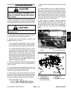
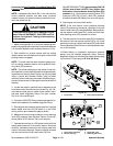
CAUTION
Prevent personal injury and/or damage to equip-
ment. Read all WARNINGS, CAUTIONS and Pre-
cautions for Hydraulic Testing at the beginning
of this section.
1. Make sure hydraulic oil is at normal operating tem-
perature by operatingthe machinefor approximately ten
(10) minutes. Make sure the hydraulic reservoir is full.
CAUTION
Move machine to an openarea, awayfrom people
and obstructions.
2. Drive machine to an open area, lower cutting decks,
turn the engine off and apply parking brake.
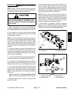
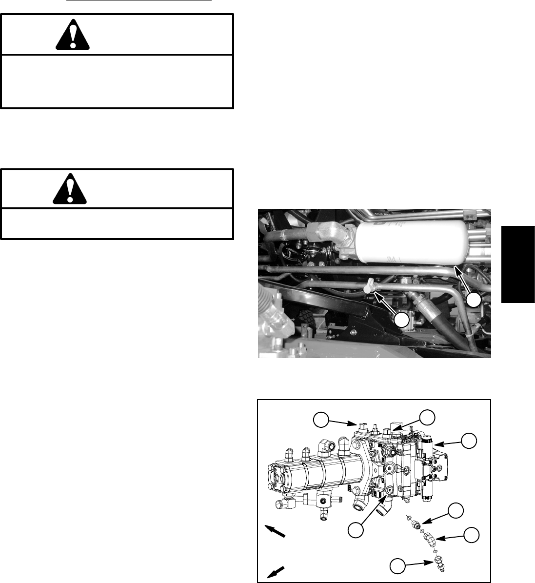
3. Locate traction circuit test fitting for function to be
checked (forward or reverse):
A. For testing the forward traction circuit, a test fit-
ting is located on a hydraulic tube on the right side of
the machine below the hydraulic oil filter (Fig. 39).
B. For testing the reverse traction circuit, a test fit-
ting needs to be temporarily installed in the piston
(traction) pump reverse traction port on left side of
pump (Fig. 40). Thoroughly clean side of pump
around plug to prevent system contamination. Re-
move plug from pump reverse traction port and then
install straight fitting, 90
o
fitting and diagnostic test
fitting into pump port (see Special Tools in this
chapter for fitting part numbers).
4. Connect a 10,000 PSI (700 bar) pressure gauge to
traction circuit test fitting for function t o be checked (for-
ward or reverse).
5. Start the engine and increase engine speed to h igh
idle speed. Make sure that traction speed is in the HI
(transport) range. Release parking brake.
6. While sitting on seat, apply brakes fully and slowly
depress the traction pedal in the appropriate direction
(forward or reverse). While pushing traction pedal, iden-
tify pressure reading on gauge as relief valve opens:
GAUGE READING TO BE:
Forward: 4100 to 4600 PSI (283 to 317 bar)
Reverse: 4750 to 5250 PSI (328 to 362 bar)
7. Release traction pedal and stop engine. Record test
results.
8. If traction pressure is too low, makes sure that by-
pass valve on traction pump is fully seated and then in-
spect traction pump relief valve in piston (traction) pump
(Fig. 40). Clean or replace valves as necessary. These
cartridge type valves are factory set and are not adjust-
able. If relief valves are in good condition, piston (trac -
tion) pump, wheel motors and/or rear axle motor should
be suspected of wear and inefficiency.
9. When testing is completed, disconnect pressure
gauge from diagnostic test fitting. If reverse traction cir-
cuit was tested, remove test fitting, 90
o
fitting and
straight fitting from piston (traction) pump. Install plug in-
to piston pump port and torque plug to 32 ft-- lb (43
N--m).
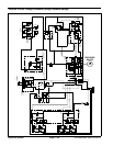
1. Oil filter 2. Forward traction fitting
Figure 39
2
1
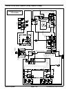
1. Traction pump
2. Forward relief valve
3. Reverse relief valve
4. Reverse traction port
5. Straight fitting
6. 90
o
fitting
7. Diagnostic test fitting
Figure 40
FRONT
RIGHT
2
3
1
4
7
6
5
Hydraulic
System