


Groundsmaster 4500--D/4700--D Hydraulic SystemPage 4 -- 109
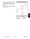
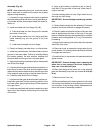
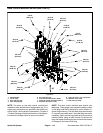
Removal (Fig. 90)
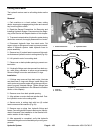
NOTE: The ports on the deck control manifold are
marked for easy identification of components. Example:
P1 is the gear pump connection port (see Hydraulic
Schematics in Chapter 9 -- Foldout Drawings to identify
the function of the hydraulic lines and cartridge valves
at each port).
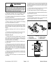
1. Park machine on a level surface, lower cutting
decks, stop engine, apply park ing brake and remove
key from the ignition switch.
2. Read the General Precautions for Removing and
Installing Hydraulic System Components at the begin-
ning of the Service and Repairs section of this chapter.
3. Unlatch and raise hood.
4. To prevent contamination of hydraulic system during
manifold removal, thoroughly clean exterior of manifold.
5. Label wire harness electrical connectors that attach
to manifold solenoid coils. Disconnect connectors from
the solenoid coils.
6. Disconnect hydraulic lines from manifold and put
caps or plugs on open hydraulic lines and fittings. Label
disconnected hydraulic lines for proper assembly.
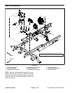
7. Remove hydraulic manifold from the frame using
Figure 90 as guide.
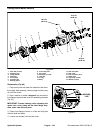
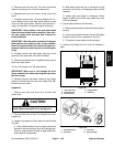
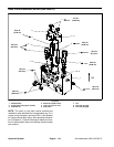
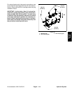
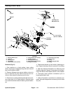
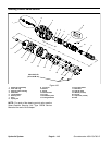
8. If hydraulic fittings are to be removed from control
manifold, mark fitting orientation to allow correct assem-
bly (Fig. 91 or 92). Remove fittings from manifold and
discard O--rings.
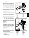
Installation (Fig. 90)
1. If fittings were removed from control manifold, lubri-
cate and place new O--rings onto fittings. Install fittings
into manifold ports using marks made during the remov-
al process to properly orientate fittings. Tighten fittings
(see Hydraulic Fitting Installation in the General Infor-
mation section of this chapter). Refer to Figure 91 or 92
for fitting installation torque.
2. Install hydraulic manifold to the frame using Figure
90 as guide.
3. Remove caps and plugs from fittings and hydraulic
lines. Properly connect hydraulic lines to manifold (see
Hydraulic Hose and Tube Installation in the General In-
formation section of this chapter).
4. Connect wire harness electrical connectors to the
solenoid valve coils.
5. Lower and secure hood.
1. Deck manifold
2. O--ring
3. Straight fitting (8 used)
4. O--ring
5. O--ring
6. Straight fitting
7. O--ring
8. Dust cover
9. Test fitting
10. O--ring
11. O--ring
12. 45
o
fitting
13. O--ring
14. Straight fitting
15. O--ring
16. 90
o
fitting
17. O--ring
Figure 91
8
4
6
3
2
1
5
7
9
10
11
14
15
12
13
16
17
11
13
GM 4500--D
50 ft--lb
(68 N--m)
75 ft--lb
(101 N--m)
75 ft--lb
(101 N--m)
1. Deck manifold
2. O--ring
3. Test fitting
4. Dust cap
5. O--ring
6. Straight fitting
7. O--ring
8. O--ring
9. Straight fitting (8 used)
10. O--ring
11. O--ring
12. Straight fitting
13. O--ring
14. O--ring
15. O--ring
16. 90
o
fitting
17. 45
o
fitting
Figure 92
8
4
6
3
2
1
5
7
9
10
14
11
15
12
16
13
17
11
13
GM 4700--D
50 ft--lb
(68 N--m)
75 ft--lb
(101 N--m)
75 ft--lb
(101 N--m)
Hydraulic
System