


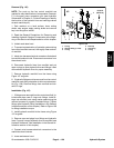
Groundsmaster 4500--D/4700--D Hydraulic SystemPage 4 -- 123
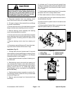
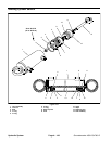
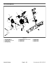
Removal (Fig. 103)
1. Park machine on a level surface, lower cutting
decks, stop engine, apply park ing brake and remove
key from the ignition switch.
2. Read the General Precautions for Removing and
Installing Hydraulic System Components at the begin-
ning of the Service and Repairs section of this chapter.
3. Unlatch and raise hood.
4. Remove four(4) cap screws andwashers u sedto se-
cure fan (item 2) to fan hub. Remove fan.
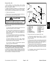
CAUTION
The radiator and engine may be hot. To avoid
possible burns, allow the engine and cooling
systems to cool before removing fan motor.
5. Remove upper radiator shroud to allow access to hy-
draulic fan m otor:
A. Remove air cleaner intake hose (item 10) from air
cleaner and plenum on top of radiator.
B. Clean junction of hydraulic tubes on right side of
upper radiator shroud. Loosen and separate hy-
draulic tubes (items 16, 17 and 18) that lead to hy-
draulic fan m otor.
C. Remove bulkhead nuts (items 21 and22) that se-
cure hydraulic tubes to upper radiator shroud. Slide
support shim (item 14) from tubes.
D. Remove fasteners that secure upper radiator
shroud to lower radiator shroud and radiator. Care-
fully lift upper shroud from machine.
E. Put caps or plugs on disconnected hydraulic
tubes to prevent contamination.
IMPORTANT: Make sure to not damage the radiator
or other machine components while loosening and
removing the fan motor a nd bracket assembly.
6. Remove six (6) cap screws a nd flange nuts that se-
cure fan motor bracket to radiator. Carefully remove fan
motor, hydraulic tubes and bracket assembly from ma-
chine and place on suitable work surface.
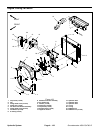
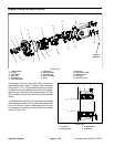
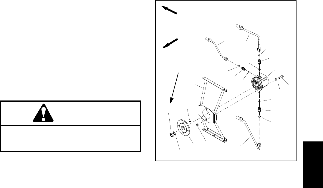
1. Hydraulic tube
2. Hydraulic tube
3. Hydraulic tube
4. Hex n ut
5. Flat washer
6. Fan hub
7. Woodruff key
8. Cap screw (2 used)
9. Flat washer ( 2 used)
10. Lock nut (2 use d)
11. Fan motor
12. Fan motor bracket
13. O--ring
14. Hydraulic fitting
15. O--ring
16. O--ring
17. Hydraulic fitting
18. O--ring
Figure 104
FRONT
RIGHT
15
1
2
3
4
7
8
9
11
5
6
10
13
12
18
17
14
16
13
15
14
27 to 33 ft--lb
(37to44N--m)
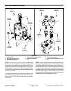
7. Remove fan motor from bracket (Fig. 104):
A. Disconnect hydraulic tubes (items 1, 2 and 3)
from fan motor fittings. Label hydraulic tubes for
proper assembly.
B. Remove hex nut (item 4) and washer (item 5) that
secure fan hub to fan motor. Use suitable puller to
carefully remove fan hub from fan motor shaft. Lo-
cate and retrieve woodruff key (item 7).
C. Remove two (2) cap screws (item 8), flat washers
(item 9) and lock nuts (item 10) that secure fan motor
to fan motor bracket. Remove fan motor from brack-
et.
D. If necessary, remove hydraulic fittings from fan
motor and discard O--rings.
Hydraulic
System