


Groundsmaster 4500--D/4700--DPage 3 -- 18Yanmar Diesel Engine
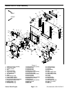
10.Support hydraulic pump assembly to prevent it from
shifting or falling. Remove fasteners that secure piston
(traction) pump to engine (see Piston (Traction) Pump
in the Service and Repairs section of Chapter 4 -- Hy-
draulic System).
11.Make sure all cable ties securing the wire harness,
fuel lines and hydraulic hoses to the engine are re-
moved.
12.Connect lift or hoist to the lift brackets on engine.
13.Remove flange nuts, rebound washers and cap
screws that secure the engine mount brackets to the en-
gine mounts.
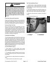
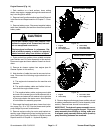
CAUTION
One person should operate lift or hoist while a
second person guides the engine out of the ma-
chine.
IMPORTANT: Make sure to not damage the engine,
fuel lines, hydraulic lines, electrical harness or oth-
er parts while removing the engine.
14.Carefully move engine away from the hydraulic
pump assembly to disengage the pump input shaft from
the coupler on the engine flywheel. Once the engine has
cleared the hydraulic pump, carefully lift engine from the
machine.
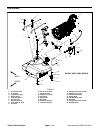
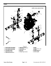
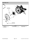
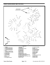
15.If necessary, remove exhaust tailpipe, tailpipe sup-
port and engine mount brackets from the engine using
Figure 14 as a guide.
Engine Installation (Fig. 14)
1. If removed, install engine mount brackets, tailpipe
support and exhaust tailpipe to the engine using Figure
14 as a guide.
2. Connect lift or hoist to the lift brackets on engine.
CAUTION
One person should operate lift or hoist while a
second p erson guides the engine into the ma-
chine.
IMPORTANT: Make sure to not damage the engine,
fuel lines, hydraulic lines, electrical harness or oth-
er parts while installing the engine.
3. Carefully lower engine into the machine and move
engine toward the hydraulic pump assembly to engage
the pump input shaft with the coupler on the engine fly-
wheel.
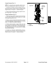
4. Align engine mount brackets to the engine mounts
(item 7). Secure engine mount brackets to engine
mounts with cap screws, rebound washers and flange
nuts.
5. Secure hydraulic pump assembly to engine (see Pis-
ton (Traction) Pump in the Service and Repairs section
of Chapter 4 -- Hydraulic System).
6. Position lower radiator shroud to radiator/oil cooler
(see Radiator and Oil Cooler Assembly in this section).
Install fasteners to secure lowershroudtoradiator.Do
not fully tighten fasteners until after engine cooling fan
motor, fan and upper shroud are installed.
7. Install engine cooling fan motor and bracket as-
sembly, cooling fan and upper radiator shroud to ma-
chine (see Engine Cooling Fan Motor in the Service and
Repairs section of Chapter 4 -- Hydraulic System). Make
sure that clearance between shrouds and fan is at least
0.180” (4.6 mm) at all points. Also, make sure that all
fasteners for radiator shrouds are fully tightened.
8. Remove caps from fuel hoses and injector pump fit-
tings that were placed during engine removal to prevent
contamination. Connect fuel supply and return hoses to
injection pump (Fig. 15 or 16). Secure hoses with hose
clamps.
9. Connect the following engine electrical components:
A. The engine wire harness to the machine wire har-
ness.
B. The positive battery cable and fusible link har-
ness to the engine starter motor.
C. The negative battery cable, engine ground cable
and main wire harness ground wires to the right side
of the engine below the starter motor with external
lock washer and cap screw. Lock washer should be
positioned next to engine casting.
10.Using notes taken during engine removal, secure
wires with cable ties in proper locations.
11.Install air cleaner system to engine (see Air Cleaner
System in this section).
12.Connect coolant hoses to the radiator. Make sure ra-
diator draincock is closed. Fill radiator and reservoir with
coolant.