


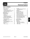

Groundsmaster 4500--D/4700--DPage 5 -- 2Electrical System
General Information
Operator’s Manual
The Operator’s Manual provides information regarding
the operation, general maintenance and maintenance
intervals for your Groundsmaster machine. Refer to the
Operator’s Manual for additional information when ser-
vicing the machine.
Electrical Drawings
The electrical schematic and wire harness drawings for
Groundsmaster 4500--D and 4700--D machines are lo-
cated in Chapter 9 -- Foldout Drawings.
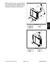
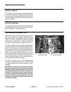
Toro Electronic Controllers (TEC)
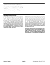
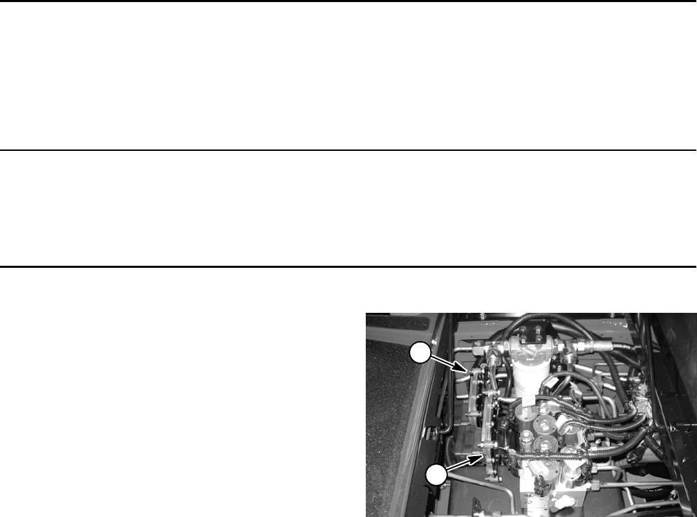
Groundsmaster 4500--D machines use a single Toro
Electronic Controller (TEC--5002) to manage machine
electrical functions. Groundsmaster 4700--D machines
uses two (2) TEC controllers for machine operation
(TEC--5002 and TEC--5001). The TEC controllers are
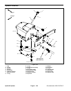
attached to a bracket under the operator seat (Fig. 1).
The TEC controllers are microprocessor controlled that
sense the condition of various switches and sensors (in-
puts). The controllers then direct electricalpower to con-
trol appropriate machine functions (outputs) based on
the input state. Communication between the TEC con-
troller(s), the Yanmar engine electronic control unit
(ECU) and the machine InfoCenter Display is provided
with a CAN--bus system. The status of inputs to the con-
trollers as well as outputs from the controllers can be
monitored with the InfoCenter Display.
The TEC controllers used on the Groundsmaster
4700--D appear identical but they are different in terms
of internal hardware and therefore c annot be inter-
changed.
IMPORTANT: To prevent machine electrical system
damage while welding o n the machine, disconnect
the battery cables from thebatteries, disconnect the
wire harness connectors from both Toro Electronic
Controllers, disconnect the wire harness connec-
tors from the engine controller and disconnect the
terminal connector from the alternator. Also, dis-
connect and remove the engine ECU from the ma-
chine before welding.
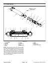
1. TEC--5002 controller 2. TEC--5001 controller
Figure 1
1
2