


Groundsmaster 4500--D/4700--DPage 5 -- 28Electrical System
Fuses
Groundsmaster 4500--D and 4700--D use numerous
fuses for circuit protection. Thefuses reside inthe power
center behind the operator’s seat.
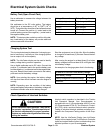
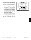
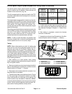
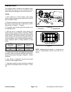
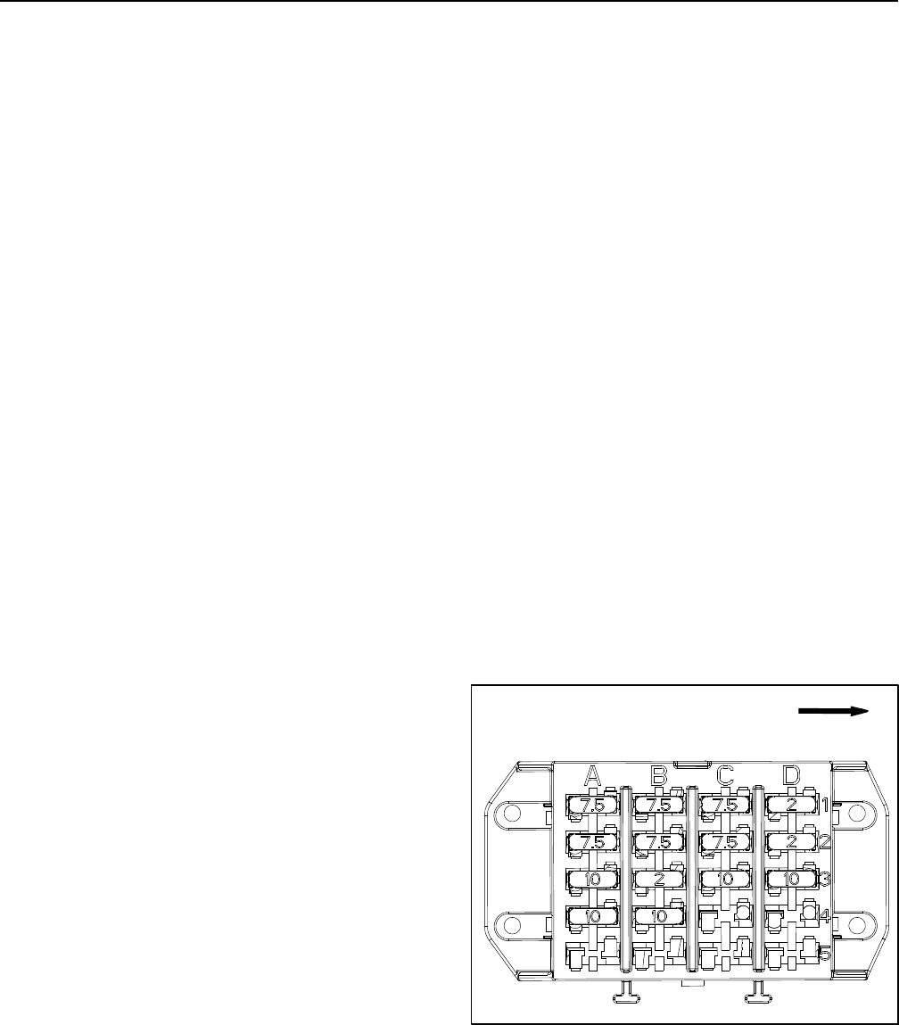
Fuse Identification and Function (Fig. 27)
Fuse A--1 (7.5 Amp) protects TEC--5002 output power
supply for engine start, engine r un, fuel pump and cool-
ing fan directional solenoid (S1).
Fuse A--2 (7.5 Amp) protects TEC--5001 output power
supply for left deck raise solenoid (S2), left deck lower
solenoid (S3), leftdeck float solenoid (S4)and right deck
raise solenoid (S7) on Groundsmaster 4700--D ma-
chines.
Fuse A-- 3 (10 Amp) protects the power supply to the
main power circuits.
Fuse A-- 4 (10 Amp) protects the power supply to the
headlight circuits.
Fuse B--1 (7.5 Amp) protects TEC--5002 output power
supply for the two (2) PTO solenoids (PRV1 and PRV2),
the cooling fan speed solenoid (PRV), counterbalance
valve (TS) and the piston (traction) pump forward and
reverse solenoids.
Fuse B--2 (7.5 Amp) protects TEC--5001 output power
supply for right deck lower solenoid (S8), right deck float
solenoid (S9), right deck engage solenoid (SV1) and left
deck engage solenoid (SV2) on Groundsmaster
4700--D machines.
Fuse B--3 (2 Amp) protects the power supply to the In-
foCenter display.
Fuse B--4 (10 Amp) protects the power supply to the op-
erator air ride seat circuit.
Fuse C--1 (7.5 Amp) protects TEC--5002 output power
supply for center decks raise solenoid (S5), center
decks float solenoid (S6) and the HI/LOW range solen-
oid.
Fuse C--2 (7.5 Amp) protects TEC--5001 output power
supply for lift/lower solenoid enable (S1) on Grounds-
master 4700--D machines.
Fuse C--3 (10 Amp) protects the power supply t o the
powerpoint.
Fuse C--4 position available for optional kit.
Fuse D--1 (2 Amp) protects logic power circuits for the
ignition switch and TEC--5002 controller.
Fuse D--2 (2 Amp) protects logic power circuits for the
TEC--5001 controller on Groundsmaster 4700--D ma-
chines.
Fuse D--3 (10 Amp) protects the power supply to the en-
gine control unit (ECU).
Fuse D--4 position available for optional kit.
Maxi--fuse M1 (60A) supplies power to the operator cab
(if equipped).
Fuse Testing
1. Make sure that ignition switch is OFF and key is re-
moved from switch.
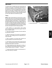
2. Open power center cover from operator platform to
access fuses.
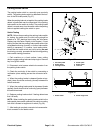
3. Remove fuse from fuse block for testing. Fuse
should have continuity across the terminals.
4. After fuse testing is completed, install known good
fuse into fuse block.
5. Close and secure power center cover.
Figure 27
FRONT