


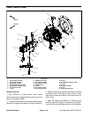
Groundsmaster 4500--D/4700--D Hydraulic SystemPage 4 -- 79
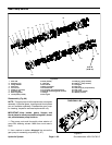
Removal (Fig. 63)
1. Park machine on a level surface, lower cutting
decks, stop engine, engage parking brake and remove
key from the ignition switch.
2. Gain access to gear pump from below the machine.
3. Drain the hydraulic reservoir into asuitable container
(see Hydraulic Reservoir in this section).
4. To prevent contamination of hydraulic system during
gear pump removal, thoroughly clean exterior of gear
pump, fittings and ends of hydraulic lines.
5. Read the General Precautions for Removing and
Installing Hydraulic System Components at the begin-
ning of the Service and Repairs section of this chapter.
6. For assembly purposes, label all hydraulic lines con-
nected to gear pump fittings.
7. Disconnect hydraulic lines from gear pump and put
caps or plugs on open hydraulic lines and fittings.
8. Support gear pump assembly to prevent it from fal-
ling.
9. Remove two(2) cap screws andwashers that secure
gearpumptopistonpump.Slidegearpumpawayfrom
piston pump until gear pump shaft is removed from pis-
ton pump coupler. Lower gear pump and remove from
machine.
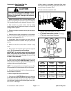
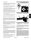
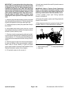
NOTE: A case drain exists in the piston (traction) pump
and a suction port is near the input shaft of the gear
pump (Fig. 64). When the gear pump is removed from
the piston pump, plug piston pump case drain hole to
prevent draining the piston pump.
10.Remove O --ring (item 15) from gear pump flange.
Discard O--ring.
11.If hydraulic fittings are to be removed from gear
pump, mark fitting orientation to allow correct assembly.
Remove fittings from pump and discard O--rings.
Installation (Fig. 63)
1. If fittings were removed from gear pump, lubricate
and place new O--rings onto fittings. Install fittings into
pump ports using marks made during the removal pro-
cess to properly orientate fittings. Tighten fittings (see
Hydraulic Fitting Installation in the General Information
section of this chapter).
2. Make sure mounting and O--ring sealing surfaces on
the gear pump and piston pump are clean.
3. Lubricate new O--ring (item 15) with clean hydraulic
oil. Position O--ring on gear pump flange.
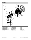
1. Piston pump case drain 2. Gear pump suction port
Figure 64
Remove plugs before installing
gear pump to piston pump
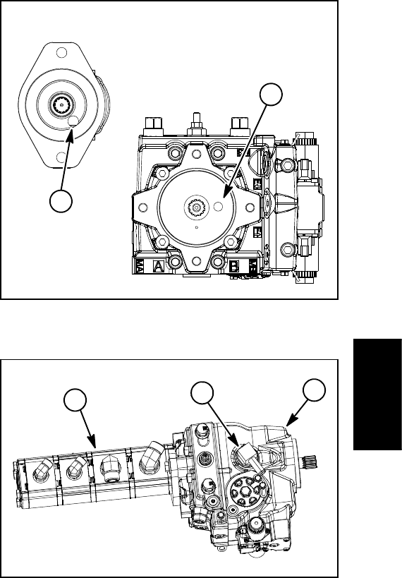
2
1
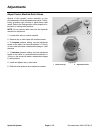
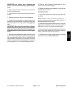
1. Piston (traction) pump
2. Ge ar pump
3. Piston pump case drain
Figure 65
2
3
1
4. Align gear teeth on gear pump input shaft with piston
pump shaft. Slide gear pump input shaft into piston
pump shaft. Secure gear pump to piston pump with two
(2) cap screws and flat washers.
IMPORTANT: Position gear pump t o the piston
(traction) pump so that the gearpump inlet (suction)
ports are facing down.
IMPORTANT: A case drain exists in the piston (trac-
tion) pump and a suction port is near the input shaft
of the gear pump (Fig. 64). Before the gear pump is
installed to the piston pump, make sure that plugs
placed in either of these ports are removed. Failure
to remove plugs will cause excessive pressure in
the piston pump and damage seals. Also, before se-
curing gear pump to piston pump, fill piston pump
housing with clean hydraulic oil through case drain
hole.
Hydraulic
System