


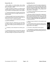
Groundsmaster 4500--D/4700--DHydraulic System Page 4 -- 114
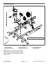
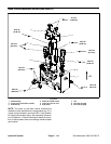
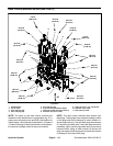
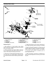
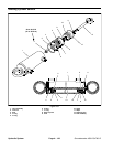
Steering Control Valve
1. Steering wheel cover
2. Lock nut
3. Steering wheel
4. Flat washer
5. Socket head screw (4 used)
6. Flange head screw (4 used)
7. Steering column
8. Steering control valve
9. Socket head screw (4 used)
10. Flange nut (4 used)
11. Tinnerman nut (4 used)
12. Column brace
13. O--ring
14. Straight fitting (5 used)
15. O--ring
Figure 97
FRONT
RIGHT
2
3
5
4
7
8
9
10
11
6
13
12
1
6
6
20 to 26 ft--lb
(28to35N--m)
Antiseize
Lubricant
7to10ft--lb
(9.5 to 13.5 N--m)
14
15
Antiseize
Lubricant
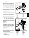
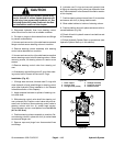
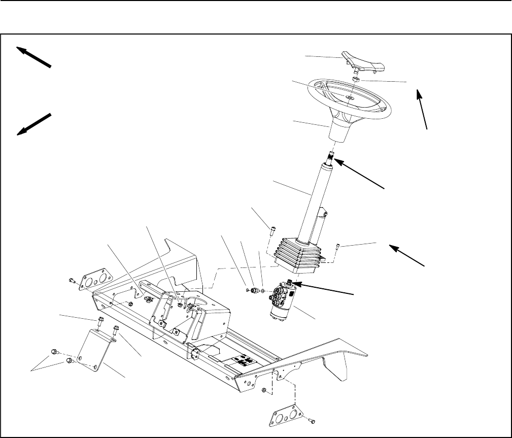
Removal (Fig. 97)
1. Park machine on a level surface, lower cutting
decks, stop engine, engage parking brake and remove
key from the ignition switch.
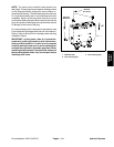
2. Remove fasteners that secure platform shroud to
front of machine (Fig. 98). Remove shroud from ma-
chine to allow access to steering control valve.
3. Remove four (4) flange head screws that secure col-
umn brace (item 12) to fr ame platform. Remove brace
from machine to allow access to steering column fasten-
ers.
4. Slide rubber bellows up from bottom of steering col-
umn. Support steering column to prevent it from falling.
5. Read the General Precautions for Removing and
Installing Hydraulic System Components at the begin-
ning of the Service and Repairs section of this chapter.
6. Thoroughly clean hydraulic connections prior to
loosening hydraulic lines.
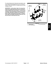
7. Label all hydraulic connections for assembly pur-
poses. Note port designations on steering control valve
(Fig. 99).