


Groundsmaster 4500--D/4700--D Hydraulic SystemPage 4 -- 29
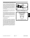
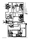
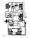
Steering Circuit
A four section gear pump is coupled to the piston (trac-
tion) pump. The third gear pump section supplies hy-
draulic flow to the steering control valve and the lift/lower
control valve. Pump hydraulicflow is delivered tothe two
circuits through a proportional flow divider located in the
fan control manifold. Steering circuit pressure is limited
to 1050 PSI (72 bar) bya relief valve located in the steer-
ing control valve.
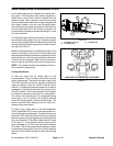
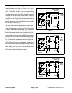
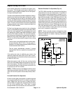
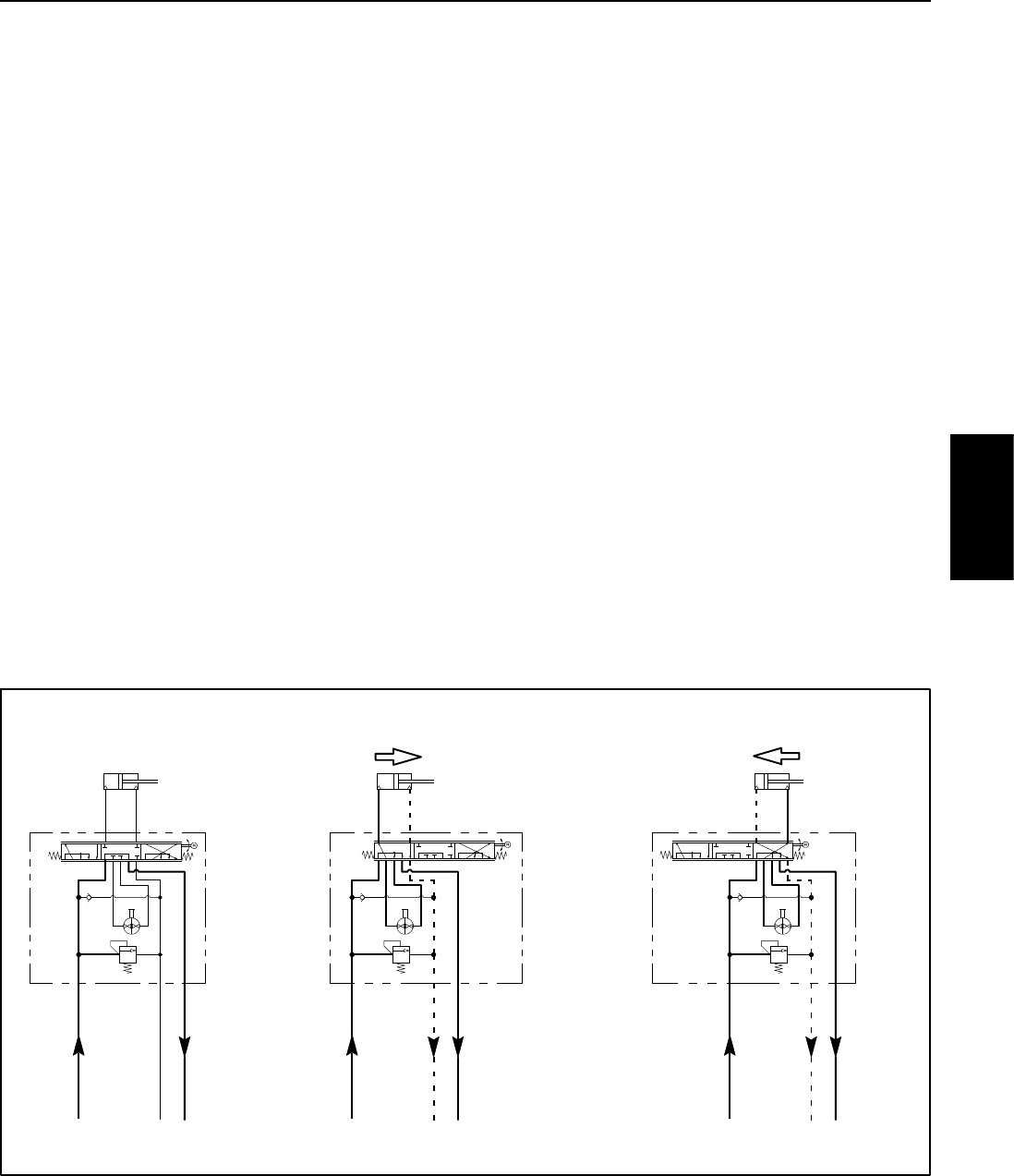
With the steering wheel in the neutral position and the
engine running, gear pump section flow enters the
steering control valve at the P port and goes through the
steering control spool valve, bypassing the rotary meter
and steering cylinder. Flow leaves the control valve
through the E port t o the oil filter and traction charge cir-
cuit.
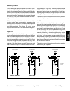
Right Turn
When a right turn is made with the engine running, the
turning of the steering wheel positions the spool valve so
that flow goes through the bottom of the spool. Flow en-
tering the steering control valve at the P port goes
through the spool and is routed to two places. First, most
of the flow through the valve is bypassed out the E port
back to the oil filter and traction charge circuit. The re-
mainder of the flow is drawn through rotary meter and
then is directed out port R. Pressure extends the steer-
ing cylinder for a right turn. The rotary meter ensures
that the oil flow to the cylinder is proportional to the
amount of the turning on the steering wheel. Fluid leav-
ing the cylinder flows back through the spool valve then
through the T port and to the hydraulic reservoir.
The steering control valve returns to the neutral position
when turning is completed.
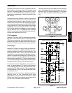
Left Turn
When a left turn is made with the engine running, the
turning of the steering wheelpositions the spool valveso
that flowgoes through the topof the spool. Flowentering
the steering control valve at the P port goes through the
spool and is routed to two places. As in a right turn, most
of the flow through the valve is bypassed out the E port
back to the oil filter and traction charge circuit. The re-
mainder of the flow is drawn through the rotary meter
and out the L port. Pressure retracts the lift cylinder for
a left turn. The rotary meter ensures that the oil flow to
the cylinder is proportional to the amount of the turning
on the steering wheel. Fluid leaving the cylinder flows
back through the spool valve then through the T port and
to the hydraulic reservoir.
The steering control valve returns to the neutral position
when turning is completed.
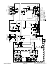
Figure 23
PISTONMOVEMENT
STEERINGCYLINDER
PISTON MOVEMENT
STEERINGCYLINDER
LEFT TURN
NEUTRAL POSITION
RIGHT TURN
NOPISTONMOVEMENT
STEERINGCYLINDER
1050
PET
R
6.1
CIR
L
CONTROL
VALVE
STEERING
PSI
1050
PET
R
6.1
CIR
L
CONTROL
VALVE
STEERING
PSI
1050
PET
R
6.1
CIR
L
CONTROL
VALVE
STEERING
PSI
Hydraulic
System