


Groundsmaster 4500--D/4700--DPage 5 -- 36Electrical System
Relays with Four (4) Terminals
Your Groundsmaster uses a number of electrical relays
that have four (4) terminals. A tag near the wire harness
relay connector can be used to identify each relay.
The main power relay is used to provide current to most
of the fuse protected circuits (operator seat, InfoCenter
display, engine electronic control unit (ECU), power
point and optional electric equipment). The main power
relayisenergizedwhentheignitionswitchisintheON
or START position.
The start relay is used to provide current to the engine
starter motor solenoid. The start relay is energized by
the engine ECU.
The air heater relay is used on models 30873 and 30874
to providec urrent for the engine air heater used forstart-
ing a cold engine. When necessary, the air heater relay
is energized by the engine ECU.
The glow relay is used on models 30881 and 30882 to
provide current to the engine glow plugs when ener-
gized by the engine ECU.
If machine is equipped with a operator cab, the cab pow-
er relay provides current to the operator cab electrical
components. The cab power relay is energized when
the ignition switch is in t he ON or START position.
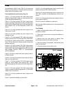
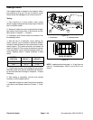
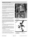
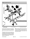
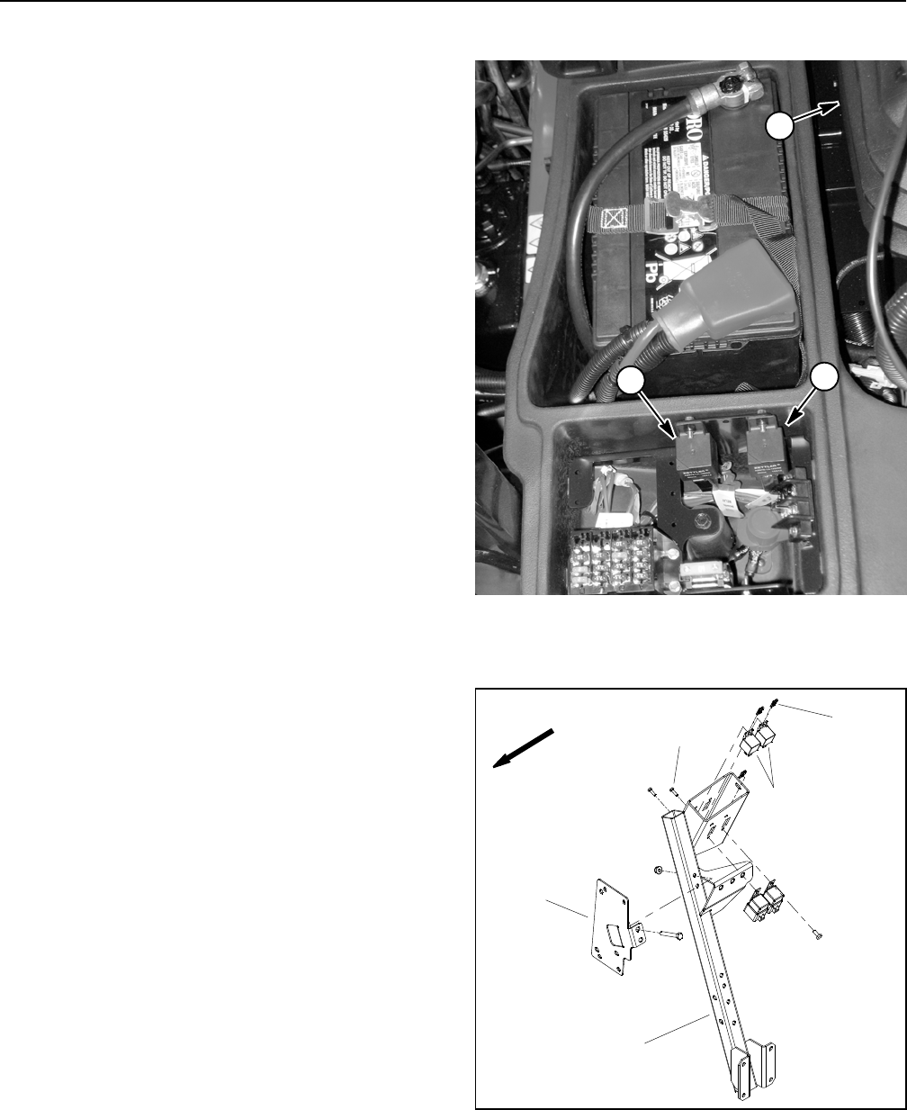
The main p ower and operator cab power (if equipped)
relays reside in the power center behind the operator’s
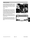
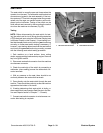
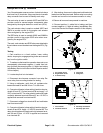
seat (Fig. 41). The start, air heater and glow relays are
attached to the air cleaner mount bracket near the en-
gine ECU (Fig. 42).
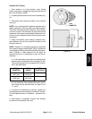
Testing
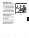
1. Park machine on a level surface, lower cutting
decks, stop engine, engage parking brake and remove
key from the ignition switch.
2. To make sure that machine operation does not occur
unexpectedly, disconnect negative (--) cable from bat-
tery and then disconnect positive (+) cable from battery
(see Battery Service in the Service and Repairs section
of this chapter).
3. Locate relay that is to be tested.
4. Disconnect wire harness connector from relay. Re-
move relay from mounting bracket for testing.
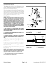
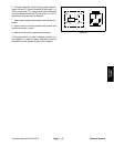
5. Using a multimeter, verify that coil resistance be-
tween terminals 86 and 85 is approximately 72 ohms.
1. Operator seat
2. Main power relay
3. Cab power relay
Figure 41
1
3
2
1. Air cleaner mount
2. Engine ECU mount
3. 4 terminal relay
4. Screw
5. Tinnerman nut
Figure 42
5
1
3
2
4
FRONT