


Groundsmaster 4500--D/4700--DPage 5 -- 30Electrical System
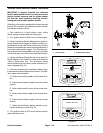
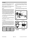
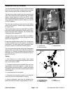
PTO Switch
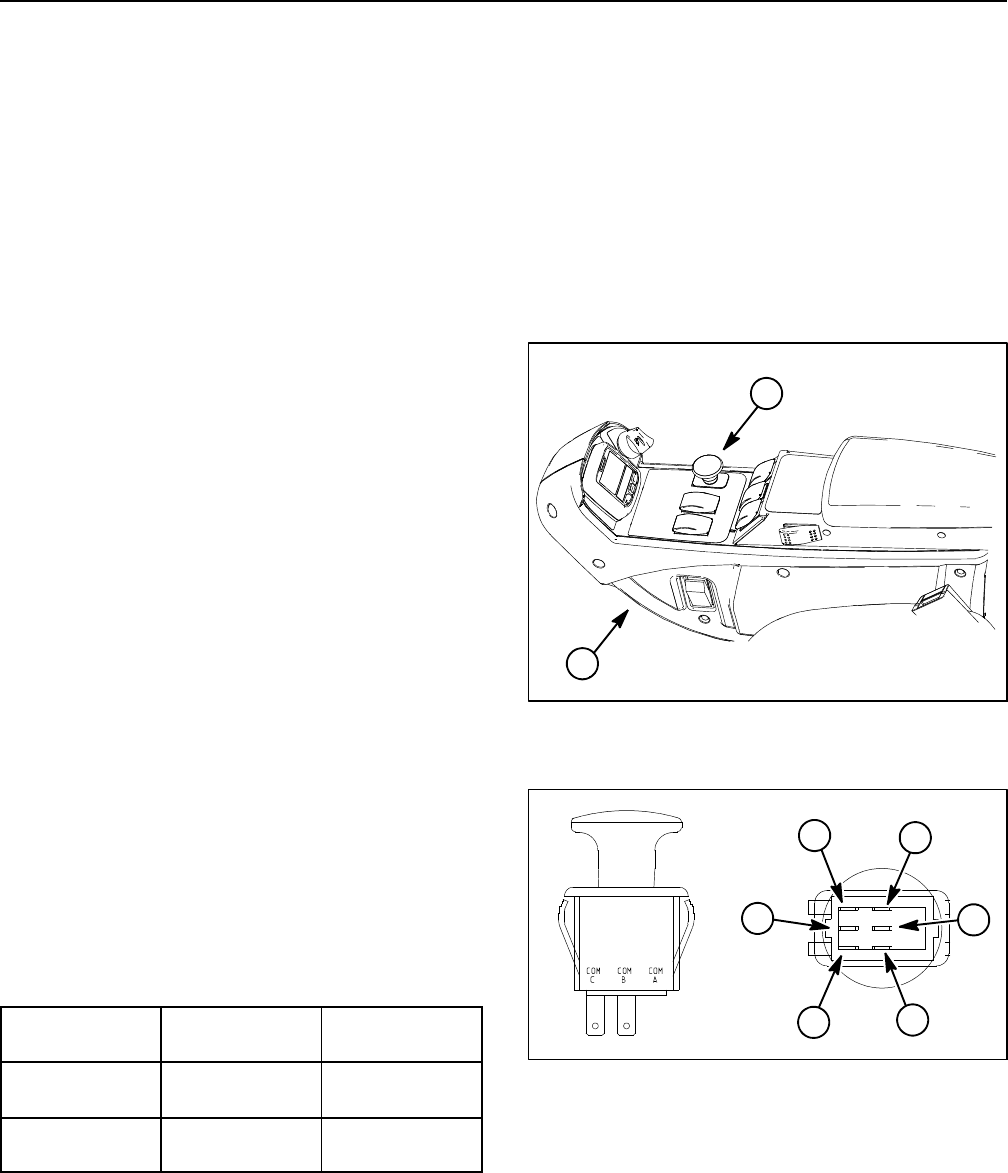
The two position PTO switch is located on the console
arm (Fig. 30). The PTO switch is pulled up to engage the
PTO and pushed in to disengage the PTO.
NOTE: To engage the PTO, the seat has to be occu-
pied, traction speed has to be in low range (mow) and
thecuttingdeckshavetobefullylowered.
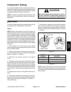
Testing
NOTE: Before disconnecting the PTO switch for test-
ing, the switch and its circuit wiring should be tested as
a TEC electrical input using the InfoCenter Display (see
InfoCenter Display in this chapter). If input testing veri-
fies that the PTO switch and circuit wiring are function-
ing correctly,no further PTO switch testing is necessary.
If, however, input testing determines that thePTO switch
and circuit wiring are not functioning correctly, proceed
with the following PTO switch testing procedure.
1. Park machine on a level surface, lower cutting
decks, engage parking brake and stop engine. Remove
key from ignition switch.
2. Remove console arm covers to gain access to PTO
switch (see Console Arm in the Service and Repairs
section of Chapter 7 -- Chassis).
3. Disconnect wire harness electrical connector from
the PTO switch.
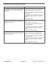
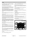
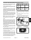
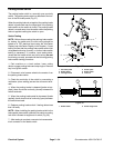
4. The switch terminals are marked as s hown in Figure
31. The circuit logic of the PTO switch is shown in the
chart below. With the use of a multimeter (ohms setting),
the switch functions can be t ested to determine whether
continuity exists between the various terminals for each
switch position. Verify continuity between switch termi-
nals. Replace switch if testing identifies that switch is
faulty.
SWITCH
POSITION
CLOSED
CIRCUITS
OPEN
CIRCUITS
OFF (DOWN) COM B + NC B
COM C + NC C
COM B + NO B
COM C + NO C
ON (UP) COM B + NO B
COM C + NO C
COM B + NC B
COM C + NC C
5. If PTO switch tests correctly and circuit problem still
exists, check wire harness (see Electrical Schematics
and Wire Harness Drawings in Chapter 9 -- Foldout
Drawings).
6. After testing is completed, connect the wire harness
connector to the PTO switch.
7. Assemble console arm (see Console Arm Assembly
in the Service and Repairs section of Chapter 7 -- Chas-
sis).
1. Console arm 2. PTO switch
Figure 30
1
2
1. COM B terminal
2. NO B terminal
3. NC B terminal
4. COM C terminal
5. NO C terminal
6. NCCterminal
Figure 31
2
3
1
6
4
5