


Groundsmaster 4500--D/4700--DPage 5 -- 48Electrical System
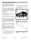
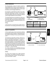
CAN--bus Termination Resistor
System communication between electrical components
on Groundsmaster 4500--D and 4700--D machines is
accomplished on a CAN--bus communication system.
Two (2) specially designed, twisted cables f orm the bus
for the network used on the machine. These wires pro-
vide the data pathways between machine components.
At the end of the twisted pair of bus cables near the In-
foCenter disp lay is a 120 ohm termination resistor.
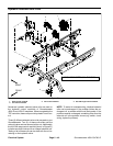
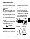
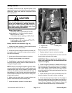
The CAN--bus termination resistor plugs into the plat-
form wire harness in the control arm. Theresistor can be
accessed by removing the cover plate on the right side
of the control arm. The wire harness connector has a
blue insert to identify the proper location for the termina-
tion resistor.
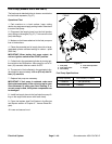
NOTE: The Groundsmaster 4500--D and 4700--D en-
gine ECU includes thesecond CAN--bus system termin-
ation resistor. This resistor cannot be accessed for
testing.
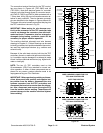
NOTE: Refer to the Electrical Schematics and Wire
Harness Drawings in Chapter 9 -- Foldout Drawings for
additional information on termination resistor location
and wire connections.
IMPORTANT: The termination resistor is required
for proper electrical system operation.
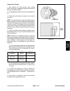
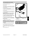
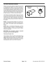
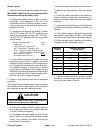
Termination Resistor Test
Theterminationresistor(Fig.59)canbetestedusinga
digital multimeter (ohms setting). There should be 120
ohms resistance between terminals A and B of the ter-
mination resistor. There is not a terminal in cavity C on
Groundsmaster 4500--D and 4700--D machines.
Figure 59
Termination
A
B
C
Resistor