


Groundsmaster 4500--D/4700--D Page 5 -- 49 Electrical System
Diode Assemblies
The Groundsmaster engine wire harness contains a
diode assembly that is used for circuit protection from
voltage spikes when the engine starter solenoid is de--
energized. This diode assembly plugs into the engine
wire harness near the engine starter motor.
Groundsmaster models 30873 and 30874 use an addi-
tional diode assembly in the engine wire harness that
protects the engine EGR circuit from reverse polarity.
This diode assembly plugs into the engine wire harness
near the en gine electronic control unit (ECU).
The diode assemblies can be identified by a black color
and a diode symbol on the end of the diode assembly
body.Refer to the engine wire harness drawing in Chap-
ter 9 -- Foldout Drawings for additional information on di-
ode assembly location.
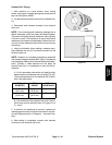
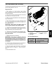
Testing
A diode assembly can be tested using a digital multime-
ter (diode test or ohms setting) and the table to the right.
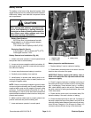
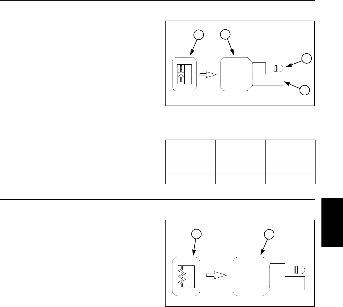
Figure 60
1. Diode
2. Male t erminal
3. Female terminal
4. End of diode body
1
2
3
4
Multimeter
Red Lead (+)
on Terminal
Multimeter
Black Lead ( --)
on Terminal
Continuity
Female Male YES
Male Female NO
Resistor Assemblies
A 75 ohm resistor plugs into the console wire harness
near the ignition switch connector (see seat and console
wire harness drawing in Chapter 9 -- Foldout Drawings).
This resistor is necessary for proper ignition switch op-
eration.
The engine wire h arness also contains a 1.6K ohm res-
ister. On Groundsmaster machines with an 80 Amp al-
ternator (see Engine Specifications in Chapter 3 --
Yanmar Diesel Engine), this resister is necessary for ig-
nition switch operation. On Groundsmaster machines
witha40ampalternator,theresistorisintheenginewire
harness butit isnot included inany operatingcircuit. The
1.6K ohm resistor plugs into the wiring harness near the
engine starter motor (see engine wire harness drawing
in Chapter 9 -- Foldout Drawings).
The resistor assemblies can be identified by their gray
color, resistor symbol and Toro part number on the end
of the resistor assembly body.
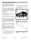
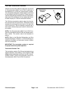
Testing
The resistor can be tested using a digital multimeter
(ohms setting). The resistance across the resistor ter-
minals should be either 75 ohms or 1.6K ohms depend-
ing on which resistor is tested.
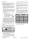
1. Resistor assembly 2. End of resistor body
Figure 61
1
2
Electrical
System