


Groundsmaster 4500--D/4700--DHydraulic S ystem Page 4 -- 102
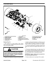
Cutting Deck Motor
The hydraulic motors used on all cutting decks are the
same.
Removal
1. Park machine on a level surface, lower cutting
decks, stop engine, engage parking brake and remove
key from the ignition switch.
2. Read the General Precautions for Removing and
Installing Hydraulic System Components at the begin-
ning of the Service and Repairs section of this chapter.
3. To prevent contamination of hydraulic system during
deck motor removal, thoroughly clean exterior of motor.
4. Disconnect hydraulic lines from deck motor. Put
caps or plugs on fittings and hoses to prevent contami-
nation of hydraulic system. Label hydraulic lines for
proper assembly.
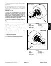
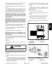
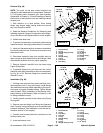
5. Remove two (2) socket head screws and flat wash-
ers that secure h ydraulic motor to cutting deck (Fig. 84).
6. Lift hydraulic motor from cutting deck.
7. Place cover on deck spindle opening to prevent con-
tamination.
8. If hydraulic fittings are to be removed from deck mo-
tor, mark fitting orientation to allow correct assembly.
Remove fittings from motor and discard O--rings.
Installation
1. If fittings were removed from deck motor, lubricate
and place new O--rings onto fittings. Install fittings into
motor ports using marks made during the removal pro-
cess to properly orientate fittings. Tighten fittings (see
Hydraulic Fitting Installation in the General Information
section of this chapter).
2. Remove cover from deck spindle opening.
3. Align splines on motor shaft and spindle shaft. Posi-
tion hydraulic motor to the cutting deck.
4. Secure motor to cutting deck with two (2) socket
head screws and flat washers (Fig. 84).
5. Remove caps or plugs from hydraulic fittings and
hoses. Connect hydraulic hoses to deck motor (see Hy-
draulic Hose and Tube Installation in the General Infor-
mation section of this chapter).
6. After assembly is completed, verify that hydraulic
hoses and fittings are not contacted by any moving com-
ponents.
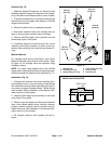
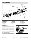
1. Socket head screw 2. Hydraulic motor
Figure 84
1
2
1
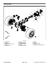
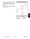
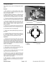
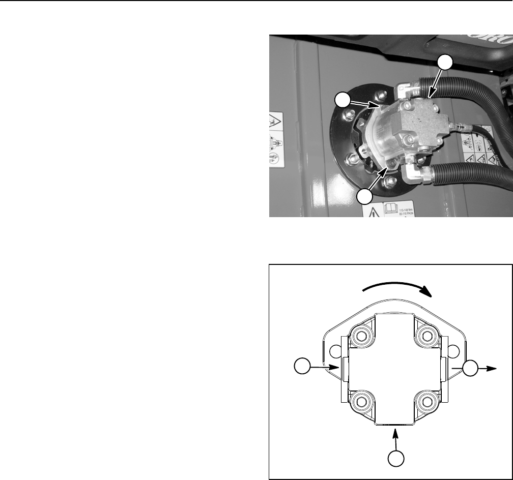
1. Flow IN
2. Flow OUT
3. Case drain
Figure 85
Rotation Di rection
2
1
3