


Groundsmaster 4500--D/4700--D Cutting DecksPage 8 -- 11
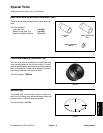
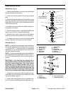
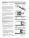
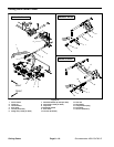
3. Using an arbor press, push the bearing cups into the
top and bottom of the spindle housing. The top bearing
cup must contact the outer bearing spacer previously
installed, and the bottom bearing cup must contact the
large snap ring. Make sure that the assembly is correct
by supporting the first bearing cup and pressing the sec-
ond cup against it (Fig 8).
4. Pack the bearing cones with grease. Apply a film of
grease on lips of oil seals.
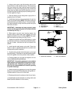
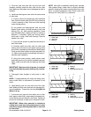
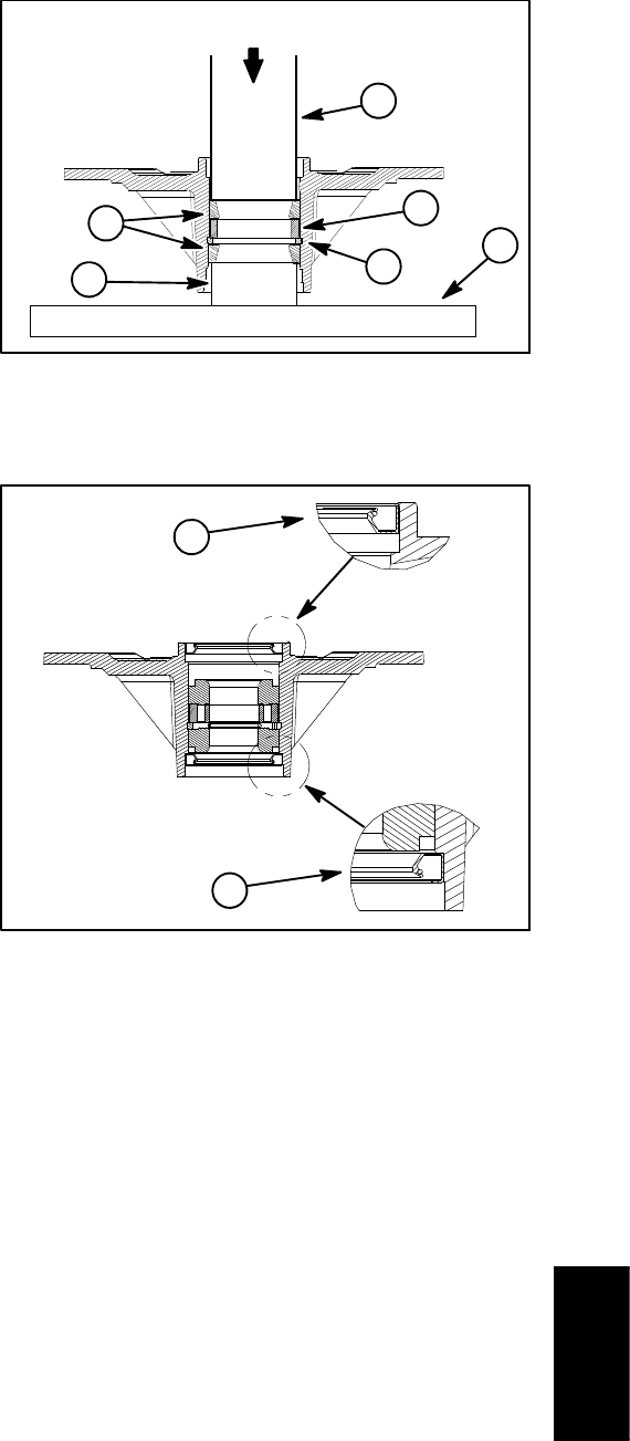
5. Install lower bearing cone and greased oil seal into
bottom ofspindle housing. NOTE:The bottomseal must
have the lip facing out (down) (Fig. 9). This seal installa-
tion allows grease to purge from the spindle during the
lubrication process.
IMPORTANT: If bearings are being replaced, make
sure to use the spacer ring that is included with the
new bearing set (Fig. 7).
6. Slide spacer ring and inner bearing spacer into
spindle housing, then install upper bearing cone and
greased oil seal into top of housing. NOTE: The upper
seal must have the lip facing out (up) ( Fig. 9).
7. Inspect the spindle shaft and shaft spacer to make
sure there are no burrs or nicks that could possibly dam-
age the oil seals. Lubricate the shaft and spacer with
grease.
8. Install spindle shaft spacer onto shaft. Place thin
sleeve or tape on spindle shaft splines to prevent seal
damage during shaft installation.
9. Carefully slide spindle shaft with spacer up through
spindle housing. The bottom oil seal and spindle spacer
should fit together when the spindle is fully installed.
10.Thread spindle nut onto shaft and tighten nut from
131 to 159 ft--lb (178 t o 215 N--m).
IMPORTANT: Pneumatic grease guns can produce
high pressure inside spindle housing that can dam-
age spindle seals. Pneumatic grease guns, there -
fore, are not recommended to be used for greasing
of spindle housings.
11.Attach a hand pump grease gun to one of the grease
fittings on housing and fill housing cavity with grease un-
til grease starts to come out of lower seal.
12.Rotate spindle shaft to make sure that it turns freely.
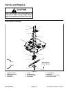
13.Install blade spindle assembly to cutting deck (see
Blade Spindle Installation in this section).
1. Bearing cup
2. Large snap ring
3. Large spacer
4. Arbor press
5. Support
6. Arbor press base
Figure 8
PRESS
2
1
3
4
6
5
1. Bottom seal installation 2. Upper seal installation
Figure 9
1
2
Cutting Decks