


Groundsmaster 4500--D/4700--DPage 5 -- 40Electrical System
Toro Electronic Controllers (TEC)
Groundsmaster 4500--D and 4700--D machines use a
Toro Electronic Controller (TEC--5002) to control electri-
cal system operation. Groundsmaster 4700--D ma-
chines use an a dditional TEC--5001 controller for
electrical control of the rear cutting decks (PTO and lift/
lower functions). The controllers are microprocessor
controlled that sense the condition of various switches
and sensors (inputs). The controllers then direct electri-
cal power to control appropriate machine functions (out-
puts) based on the input state. The controllers are
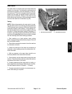
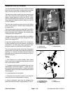
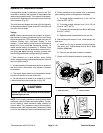
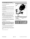
attached to a bracket under the operator seat (Fig. 47).
Logic power is provided to the controllers as long as the
battery cables are connected to the battery. A pair of 2
amp fuses (D--1 for TEC--5002 and D--2 for TEC--5001)
provide circuit protection for this logic power to the con-
trollers.
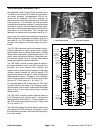
The TEC--5002 controller monitors the states of the fol-
lowing components as inputs: ignition switch, traction
pedal position sensor, parking brake switch, HI/LOW
speed switch, seat switch, engine speed switch, PTO
switch, center cutting deck lift switch, cutting deck posi-
tion switches (decks 4 and 5), hydraulic temperature
sender and hydraulic pressure transducer.
The TEC--5002 controller controls electrical output to
the engine electronic control unit (ECU) (start and run
functions), fan drive solenoid coils (direction and
speed), traction (piston) pump solenoids (forward and
reverse), t raction solenoid coil (HI/LOW speed), PTO
solenoid coils (decks 1 through 5), center cutting decks
raise/lower/float (decks 1 through 5) and counterbal-
ance. Circuit protection forfront TEC outputs is provided
bythree(3)7.5ampfuses(A--1,B--1andC--1).
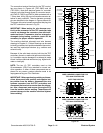
On Groundsmaster 4700--D machines, the TEC--5001
controller monitors the states of the following compo-
nents as inputs: ignition switch, cutting deck lift switches
(decks 6 and 7) and cutting deck position switches
(decks 6 and 7).
The TEC--5001 controller controls electrical output to
the PTO solenoid coils (decks 6 and 7), cutting decks
raise/lower/float ( decks 6and 7). Circuit protection for
rear TEC outputs is provided by three (3) 7.5 amp fuses
(A--2, B--2 and C--2).
The InfoCenter d isplay should be used to check inputs
and outputs of the TEC controllers. Information on using
the InfoCenter is included in the InfoCenter Display sec-
tion of this chapter.
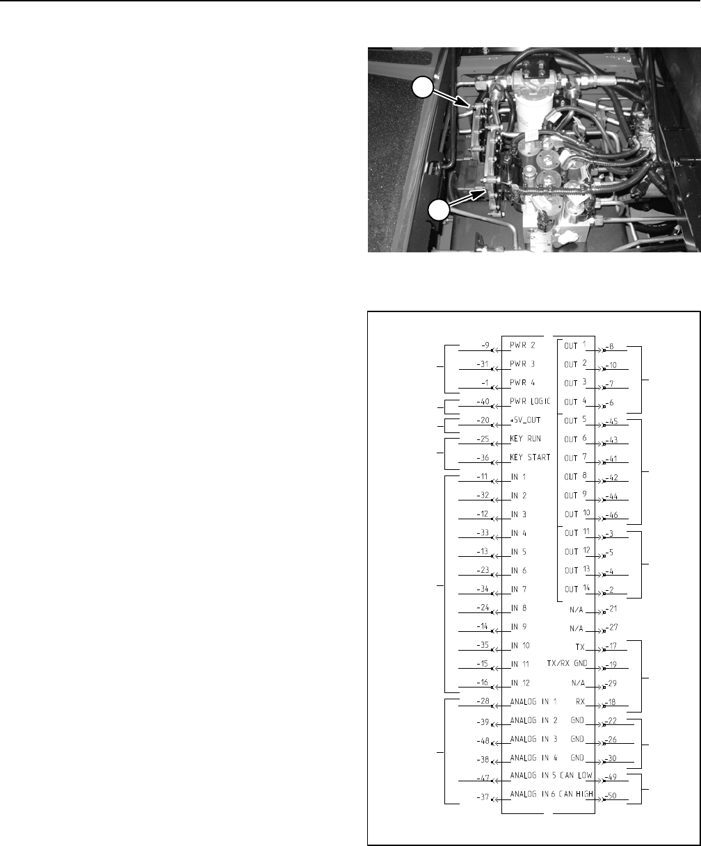
1. TEC--5002 controller 2. TEC--5001 controller
Figure 47
1
2
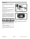
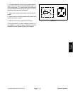
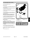
Figure 48
12V POWER
(7.5AFUSES)
12V LOGIC
IGNITION
SWITCH
INPUTS
DIGITAL
INPUTS
(OPEN/
ANALOG
INPUTS
POWER
(2AMP FUSE)
COMM
PORT
CAN BUS
CLOSED)
OUTPUTS
(PWR 2)
GROUND
(VARIABLE)
OUTPUTS
(PWR 3)
OUTPUTS
(PWR 4)
+5 VOLTAGE
OUT
TEC--5002