


Groundsmaster 4500--D/4700--D Hydraulic SystemPage 4 -- 133
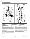
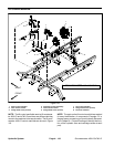
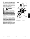
Removal (Fig. 110)
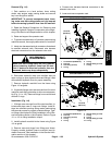
1. Park machine on a level surface, lower cutting
decks, stop engine, apply park ing brake and remove
key from the ignition switch.
IMPORTANT: To prevent unexpected deck lower -
ing, make sure that cutting decks are fully lowered
before loosening hydraulic lines from lift manifold.
2. Read the General Precautions for Removing and
Installing Hydraulic System Components at the begin-
ning of the Service and Repairs section of this chapter.
3. Raise and support the operator seat.
4. To prevent contamination of hydraulic system during
manifold removal, thoroughly clean exterior of manifold.
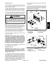
5. Label wire harness electrical connectors that attach
to manifold solenoid coils. Disconnect wire harness
electrical connectors from the solenoid valve coils.
WARNING
Make sure that cutting decks are fully lowered
before loosening hydraulic lines from lift man-
ifold. If decks are raised as hydraulic lines are
loosened, decks may drop unexpectedly.
6. Disconnect hydraulic lines from manifold and put
caps or plugs on open hydraulic lines and fittings. Label
disconnected hydraulic lines for proper assembly.
7. Remove hydraulic manifold from the frame using
Figure 110 as guide.
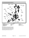
8. If hydraulic fittings are to be removed from lift control
manifold, mark fitting orientation to allow correct assem-
bly (Fig. 111 or 112). Remove fittings from manifold and
discard O--rings.
Installation (Fig. 110)
1. If fittings were removed from lift control manifold, lu-
bricate a nd place new O--rings onto fittings. Install fit-
tings into manifold openings using marks made during
the removal process to properly orientate fittings. Tight-
en fittings (see Hydraulic Fitting Installation in the Gen-
eral Information section of this chapter). Refer to Figure
111 or 112 for fitting installation torque.
2. Install hydraulic manifold to the frame using Figure
110 as guide.
3. Remove caps and plugs from fittings and hoses.
Properly connect hydraulic lines to manifold (see Hy-
draulic Hose and Tube Installation in the General Infor-
mation section of t his chapter).
4. Connect wire harness electrical connectors to the
solenoid valve coils.
5. Lower and secure operator seat.
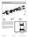
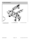
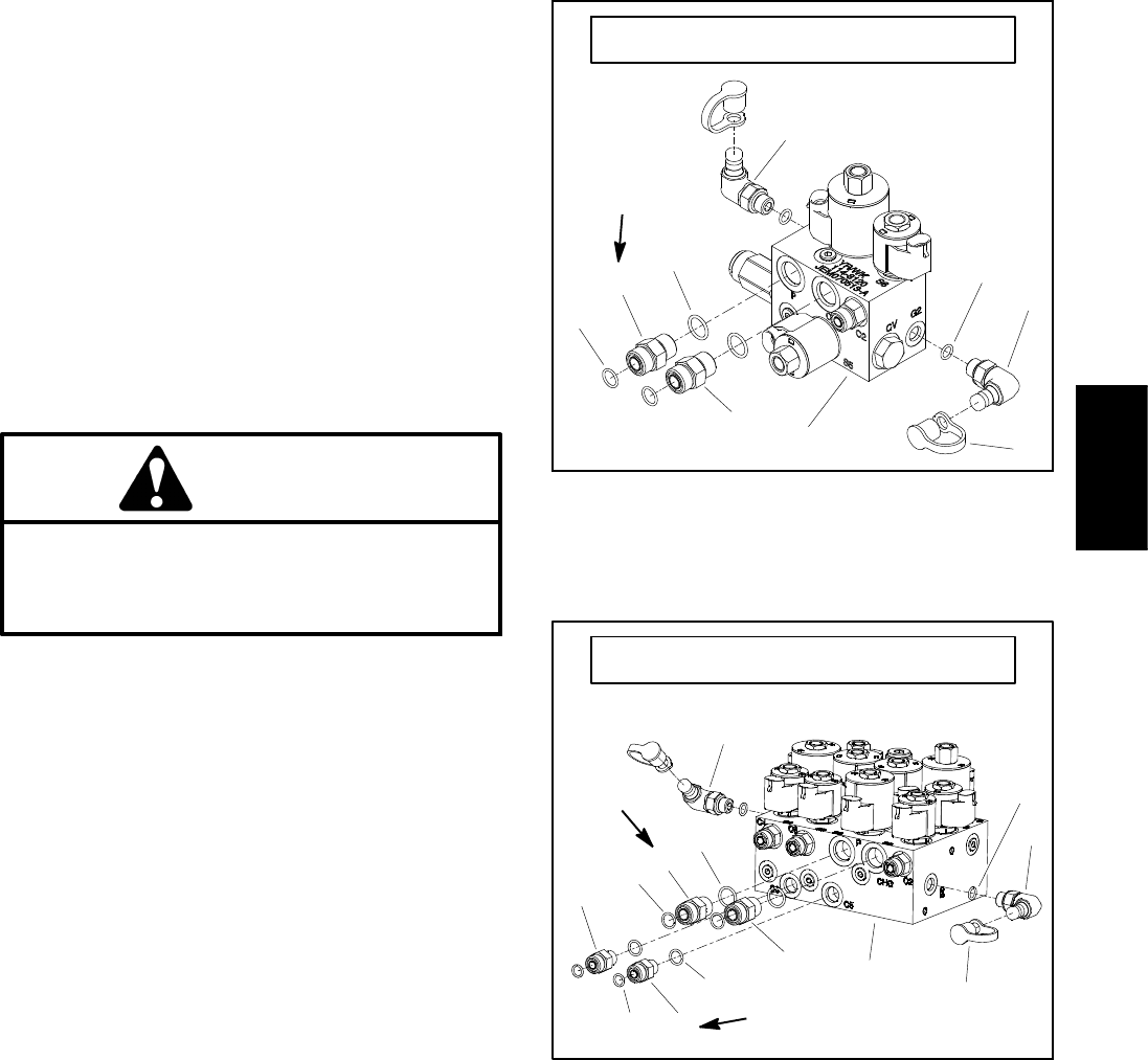
1. Lift manifold (GM4500--D)
2. Dust cap
3. Test fitting (2 used)
4. O--ring
5. O--ring
6. Straight fitting (2 used)
7. O--ring
Figure 111
4
3
2
1
5
6
7
GROUNDSMASTER 4500--D
6
3
50 ft--lb
(68 N--m)
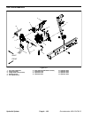
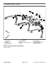
1. Lift manifold (GM4700--D)
2. Dust cap
3. Test fitting (2 used)
4. O--ring
5. O--ring
6. Straight fitting (2 used)
7. O--ring
8. O--ring
9. Straight fitting (2 used)
10. O--ring
Figure 112
GROUNDSMASTER 4700--D
4
3
2
1
5
6
7
3
6
8
9
10
9
50 ft--lb
(68 N--m)
25 ft--lb
(34 N--m)
Hydraulic
System