


Groundsmaster 4500--D/4700--D Hydraulic SystemPage 4 -- 63
Procedure for Steering Circuit Relief Pressure
Test
The steering circuit relief pressure test should be per-
formed to make sure that the steering circuit relief pres-
sure is correct.
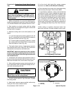
CAUTION
Prevent personal injury and/or damage to equip-
ment. Read all WARNINGS, CAUTIONS and Pre-
cautions for Hydraulic Testing at the beginning
of this section.
1. Make sure hydraulic oil is at normal operating tem-
perature by operatingthe machinefor approximately ten
(10) minutes. Make sure the hydraulic reservoir is full.
2. Park machine on a level surface with the cutting
decks lowered and off. Make sure engine is off and the
parking brake is engaged.
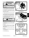
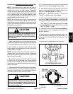
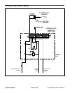
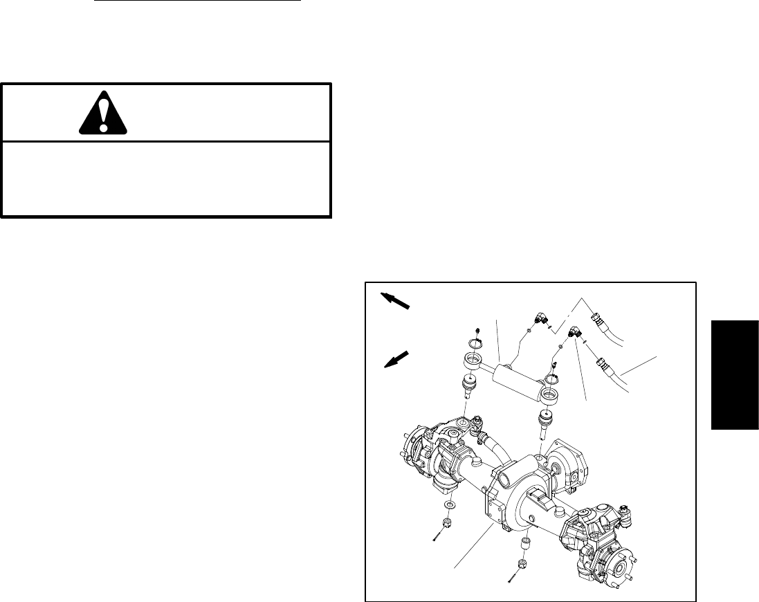
3. Thoroughly clean junction of hydraulic hose and
steering cy linder fitting at the barrel e nd of the steering
cylinder (Fig. 53). Disconnect hose from fitting in barrel
end of steering cylinder.
4. Install 5000 PSI (350 bar) pressure gauge with hy-
draulic hose attached to disconnected hose. Install steel
cap on steering cylinder fitting to prevent any leakage
from cylinder.
5. After installing pressure gauge, start engine and run
at low idle speed. Check for hydraulic leakage and cor-
rect before proceeding with test.
6. Increase engine speed to high idle speed.
IMPORTANT: While testing, rotate steering wheel
only long enough to get a system relief pressure
reading. Holding the steering circuit at relief pres -
sure for an extended period may damage the steer-
ing control valve.
7. Turn steering wheel to the right while monitoring the
pressure gauge. When steering circuit pressure reach-
es the relief pressure set ting, pressure should stabilize
briefly and then may continue to increase. The steering
circuit relief pressure is the gauge reading when pres-
sure stabilizes.
GAUGE READING TO BE 1150 TO 1500 PSI (80 to
103 bar)
8. Stop the engine. Record test results.
9. If steering relief pressure is incorrect, inspect steer-
ing relief valve located in the steering control valve (see
Steering Control Valve Service in the Service and Re-
pairs section of this chapter). If relief valve is operating
properly and if lift/lower and traction charge circuit prob-
lems also exist, the third gear pump section should be
suspected of wear or damage. If steering wheel contin-
ues to turn at end of cylinder travel (with lower than nor-
mal effort), steering cylinder or steering control valve
may be worn or damaged.
10.When testing iscomplete, turn steering wheel toboth
the right and the left with the engine not running to re-
lieve steering circuit pressure. Remove pressure gauge
from hydraulic hose and steel cap from steering cylinder
fitting. Connect hydraulic hose to steering cylinder fit-
ting.
1. Steering cy linder
2. Barrel end hose
3. Barrel end fitting
4. Rear axle
Figure 53
1
2
4
3
FRONT
RIGHT
Hydraulic
System