


Groundsmaster 4500--D/4700--D Page 7 -- 5 Chassis
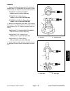
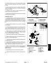
9. Loosen and remove four (4) socket head screws
(item 5) that secure s teering control valve to steering
column.
10.Loosen and remove four (4) socket head screws
(item 9) and flange nuts (item 10) that secure steering
column to machine.
11.Carefully raise steeringcolumnassemblyfrom
steering control valve and machine.
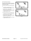
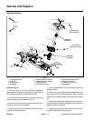
12.Disassemble steering column assembly as needed
using Figure 4 as a guide.
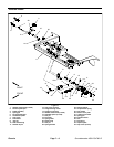
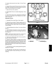
Installation (Fig. 2)
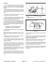
1. Assemble steering column using Figure 4as a guide.
After assembly,make sure that release pin on end of cyl-
inder shaft is positioned ag ainst the pedal. Jam n ut on
cylinder shaft can be used to adjust location of release
pin.
2. Apply antiseize lubricant to input shaft of steering
control valve.
3. Carefully slide steering column onto steering control
valve. Secure steering column in place with four (4)
socket head screws (item 9) and flange nuts (item 10).
4. Secure steering control valve to steeringcolumn with
four (4) socket head screws (item 5). Torque screws
from 7to10ft--lb(9.5to13.5N--m).
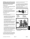
5. Slide rubber bellows to bottom of steering column.
6. Position column brace (item 12) in place and secure
with four (4) flange head screws.
7. Thoroughlyclean tapered surfaces of steering wheel
and steering column.
8. Apply antiseize lubricant to splines of steering col-
umn taking care to keep antiseize lubricant from column
taper. Slide steering wheel onto steering column.
9. Secure steering wheel to steering column with flat
washer and lock nut. Torque hex nut from 20 to 26 ft--lb
(28to35N--m).
10.Install steering wheel cover to steering wheel.
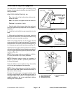
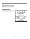
11.Install and secure platform s hroud to machine (Fig.
3).
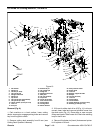
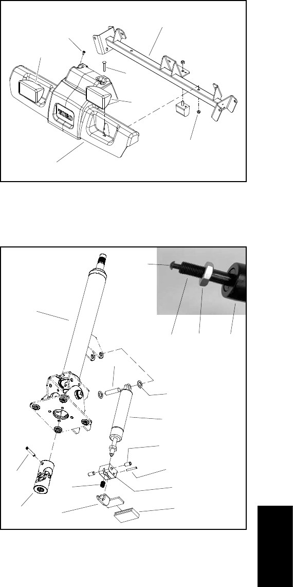
1. Roller support
2. Screw (2 used)
3. Carriage screw (2 u sed)
4. He adlight assembly
5. Flange nut (2 used)
6. Platform shroud
Figure 3
2
3
4
5
6
1
4
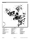
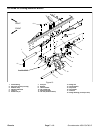
1. Steering column
2. Pin
3. Universal j oint
4. Pin
5. Lock washer (2 used)
6. Cylinder
7. Bolt (2 used)
8. Pin
9. Pedal block
10. Pedal cover
11. Pedal
12. Spring
13. Release pin
14. Cylinder shaft
15. Jam nut
Figure 4
2
3
4
5
6
1
7
8
9
10
12
11
6
13
14 15
Chassis