


Groundsmaster 4500--D/4700--D Page 5 -- 41 Electrical System
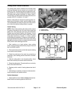
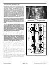
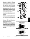
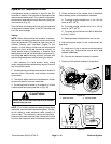
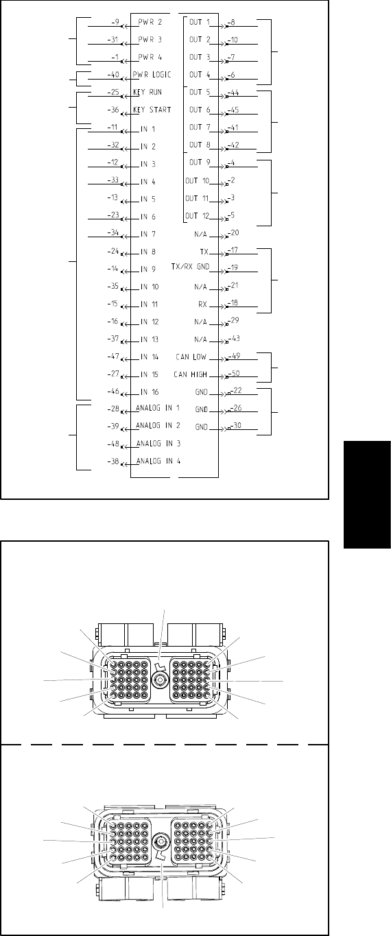
The connection terminal functions for the TEC c ontrol-
lers are shown in Figures 48 (TEC--5002) and 49
(TEC--5001). Note that electrical power for controller
outputs is provided through three (3) connector termin-
als (PWR 2, PWR 3 and PWR 4) each protected with a
7.5 amp fuse. A fifty (50) pin wire harness connector at-
taches to each controller. The wire harness connector
pins are identified in the diagram in Figures 48 and 49.
The layout of the wire harness connectors that plug into
the TEC controllers is shown in Fig. 50.
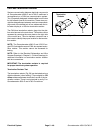
IMPORTANT: When testing for wire harness con-
tinuity at the connector for the TEC controller, take
care to not damage the connector pins with multi-
meter test leads. If connector pins are enlarged or
damaged during testing, connector repair will be
necessary for proper machine operation.
The machine electrical schematic and wire harness
drawings in Chapter 9 -- Foldout Drawings can be used
to identify possiblecircuit problems between the control-
lers and the input/output devices (e.g. switches and
solenoid coils).
Because of the solid state circuitry built into the TEC
controllers, there is no method to test a controller direct-
ly. A controller may be damaged if an attempt is made
to test it with an electrical test device (e.g. digital multi-
meterortestlight).
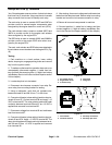
NOTE: The two (2) TEC controllers used on the
Groundsmaster 4700--D are matched for correct ma-
chine operation. If either of these components are re-
placed for any reason, system software needs to be
reprogrammed by your Toro Distributor.
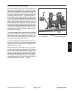
IMPORTANT: Before performing welding on thema-
chine, disconnect both positive and negative bat-
tery cables from the battery, disconnect the wire
harness connector from the TEC controllers and
disconnect the terminal connector from the alterna-
tor. Also, disconnect and remove the engine ECU
from the machine before welding. These steps will
prevent damage to the machine electrical system
when welding.
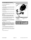
Figure 49
12V POWER
(7.5AFUSES)
12V LOGIC
IGNITION
SWITCH
INPUTS
DIGITAL
INPUTS
(OPEN/
ANALOG
INPUTS
POWER
(2AMP FUSE)
COMM
PORT
CAN BUS
CLOSED)
OUTPUTS
(PWR 2)
GROUND
(VARIABLE)
OUTPUTS
(PWR 3)
OUTPUTS
(PWR 4)
TEC--5001
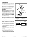
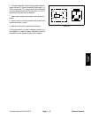
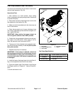
Figure 50
WIRE HARNESS CONNECTOR FOR
TEC--5002 CONTROLLER
1
11
21
31
41
30
20
10
40
50
NOTE TAB POSITION
1
11
21
31
41
30
20
10
40
50
NOTE TAB POSITION
WIRE HARNESS CONNECTOR FOR
TEC--5001 CONTROLLER
Electrical
System