


Groundsmaster 4500--D/4700--D Page 7 -- 11 Chassis
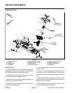
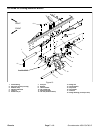
5. Loosen and remove lock nut (item 11) from lift arm
pivot pin.
6. Support lift arm and pull lift arm pivot pin from lift arm
and frame.Locate and remove thrust washers from both
sides of lift arm during pivot pin removal.
7. Remove lift arm from machine.
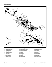
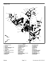
8. Disassemble lift arm as needed using Figure 10 as
a guide.
9. Clean lift arm and pivot pin. Inspect lift arm bushings
and pivot pin for damage or wear. Replace worn or dam-
aged components.
Installation (Fig 10)
1. Assemble lift arm using Figure 10 as a guide.
2. Position lift arm to frame. Fit thrust washer (item 10)
between both sides of lift arm and frame. Slide pivot pin
into frame and lift arm. Align roll pin in pivot pin with slot
in frame flange.
3. Install and tighten lock nut (item 11) to secure lift arm
pivot pin.
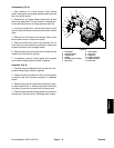
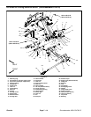
4. Install hydraulic lift cylinder to lift arm with cylinder
pin. Secure cylinderpin tolift arm withflange head screw
and flange nut.
NOTE: Install thrust washer (item 33) on carrier pivot
shaft before installing cutting deck on pivot shaft.
5. Position and install cutting deck to lift arm (see Cut-
ting Deck Operator’s Manual).
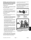
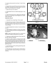
6. If lift arm for either deck #4 or #5 was r emoved, slide
hydraulic hoses through the hose retaining loop on the
lift arm. Remove caps and plugs from hydraulic hoses
and fittings and install hoses to the deck motor (Fig. 12).
Make sure that deck is fully lowered to the ground before
tightening hoses.
7. Lubricate lift arm and lift cylinder grease fittings after
assembly is complete.
8. After assembly, raise and lower the cutting deck to
verify that hydraulic hoses and fittings do not contact
anything.
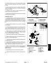
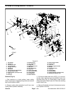
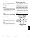
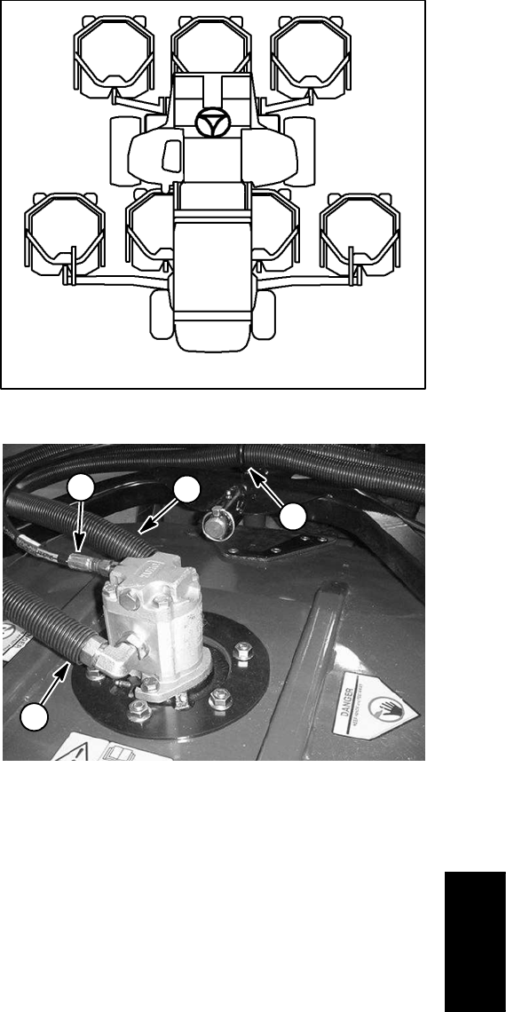
Figure 11
#4 Deck #1 Deck #5 Deck
#7 Deck
(GM4700)
#6 Deck
(GM4700)
#3
Deck
#2
Deck
CUTTING DECK LOCATIONS
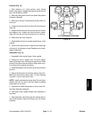
1. Supply hose
2. Return hose
3. Case drain hose
4. Hose retaining loop
Figure 12
2
4
1
3
Chassis