


Groundsmaster 4500--D/4700--D Hydraulic SystemPage 4 -- 85
5. For assembly purposes, label all hydraulic lines con-
nectedtogearpumpandtractionpumpfittings.
6. Put a drain pan below the pump assembly. Remove
hydraulic hoses connected to piston and gear pumps.
Put plugs or caps on disconnected hydraulic hoses and
fittings to prevent contamination of the system.
7. Remove gear pump from machine (see Gear Pump
in this section).
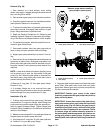
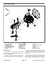
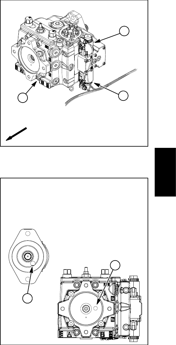
NOTE: A case drain exists in the piston (traction) pump
and a suction port is near the input shaft of the gear
pump (Fig. 70). When the gear pump is removed from
the piston pump, plug piston pump case drain hole to
prevent draining the piston pump.
IMPORTANT: Dry weight of piston (traction) pump
is 90 pounds (41 kg).
8. Support the piston pump to prevent it from falling
while removing two (2) cap screws and washers retain-
ing pump a ssembly to engine flywheel plate. Carefully
pull pump assembly from flywheel plate and lower it out
of the machine.
9. If hydraulic fittings are to be removed from piston
pump, mark fitting orientation to allow correct assembly.
Remove fittings from pump and discard O--rings.
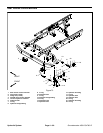
Installation (Fig. 68)
1. If fittings were removed from piston pump, lubricate
and place new O--rings onto fittings. Install fittings into
pump ports using marks made during the removal pro-
cess to properly orientate fittings. Tighten fittings (see
Hydraulic Fitting Installation in the General Information
section of this chapter).
IMPORTANT: To prevent spring coupler damage,
make sure that piston pump is properly supported
and does not putside loadinto coupler duringpump
installation.
2. Carefully raise piston pump into the machine, align
pump input shaft to spring coupler on engine and posi-
tion it to the engine flywheel plate. Support pump to pre-
vent it from producing any side load into coupler and
also to align pilot diameter of pump to flywheel plate
bore.
3. While maintaining pump alignment with spring cou-
pler and flywheel plate, install two (2) cap screws and
washerstosecurepistonpumptoengine.
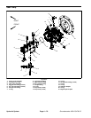
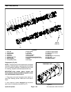
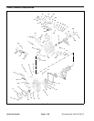
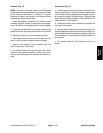
1. Piston pump
2. Solenoid coil (forward)
3. Solenoid coil (reverse)
Figure 69
2
3
1
FRONT
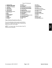
1. Piston pump case drain 2. Gear pump suction port
Figure 70
after gear pump is removed.
2
1
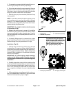
drain and gear pump suction port
install plugs in piston pump case
To prevent draining the pumps,
Remove plugs before installing
gear pump to piston pump
Hydraulic
System