


Groundsmaster 4500--D/4700--D Hydraulic SystemPage 4 -- 137
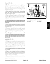
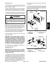
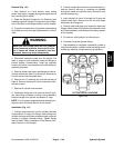
NOTE: The lift control manifold uses several zero leak
plugs. These plugs have a tapered sealing surface on
theplugheadthatisdesignedtoresistvibrationinduced
plug loosening. The zero leak plugs also have an O--ring
as a secondary seal. If zero leak plug removal is neces-
sary, lightly rap the plug head using a punch and ham-
mer before using an allen wrench to remove the plug:
the impact will allow plug removal with less chance of
damage to the socket head of the plug.
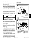
WARNING
If lift manifold is attached to machine, make sure
that cutting decks are fully lowered before loos-
ening hydraulic lines, cartridge valves or plugs
from lift manifold. If decks are raised as compo-
nents are loosened, decks may drop unexpect-
edly.
For solenoid and control valve service procedures, see
Control Manifold Cartridge Valve Service in this section.
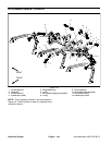
Refer toFigures 114 and 115 for cartridge valve and plug
installation torque.
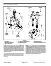
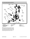
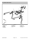
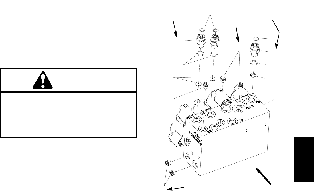
IMPORTANT: A flow control orifice is placed be-
neath several of the hydraulic fittings on the lift con-
trol manifold (Fig. 115). The liftmanifold uses two (2)
different orifice sizes. If a fitting is removed from the
lift control manifold and an orifice is in the manifold
port, make sure to remove orifice and label its posi-
tion for assembly purposes. Also note location of
groove in orifice for assembly purposes.
IMPORTANT: When installing orifice in manifold
(Fig. 115), make sure that orifice is flat in the base of
the manifold port. Manifold damage is possible if
the orifice is cocked in the cavity.
1. Manifold body
2. Straight fitting (3 used)
3. Zero leak plug (#4)
4. Orifice (0.063)
5. Orifice (0.080)
6. O--ring
7. O--ring
Figure 115
4
6
3
2
1
5
2
3
3
UP
6
7
7
25 ft--lb
(34 N--m)
20 ft--lb
(27 N--m)
25 ft--lb
(34 N--m)
20 ft--lb
(27 N--m)
Hydraulic
System