


Groundsmaster 4500--D/4700--D Page 5 -- 35 Electrical System
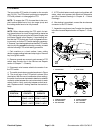
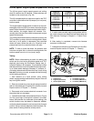
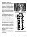
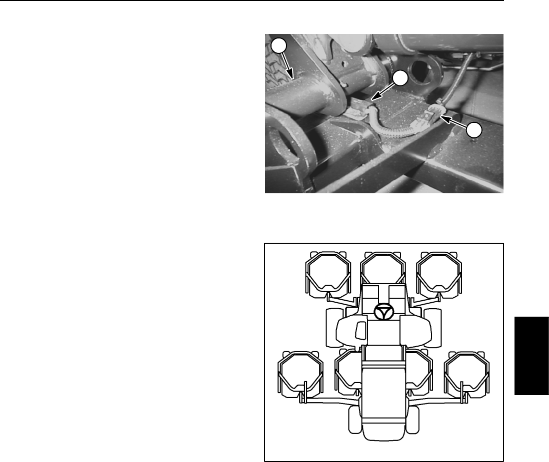
Cutting Deck Position Switches
The cutting deck position switches are normally open
proximity switches that are located on the traction unit
frame (Fig. 39). The sensing plate is located on the cut-
ting deck lift arm. The Groundsmaster 4500 --D usestwo
(2) cutting deck position switches: f or decks 4 and 5.
There arefour (4) deck positionswitches on theGround-
smaster 4700--D: for decks 4, 5, 6 and 7.
When a cutting deck is lowered, the sensing plate is lo-
cated near the position switch and the switch closes.
This closed switch provides an input for the TEC control-
ler to allow the lowered cutting decks to operate.
Switch Testing
NOTE: Before disconnecting the deck position switch
for testing, the switch and its circuit wiring should be
tested as a TEC electrical input using the InfoCenter
Display (see InfoCenter Display in this chapter). If input
testing verifies that the deck position switch and circuit
wiring are functioning correctly, no further position
switch testing is necessary. If, however, input testing de-
termines that the deck position switch and circuit wiring
are not functioning correctly, proceed with the following
deck position switch testing procedure.
1. Park machine on a level surface, lower cutting
decks, engage parking brake and stop engine. Remove
key from ignition switch.
2. Disconnect deck position switch that requires testing
from machine wire harness.
3. Check the continuity of the switch by connecting a
multimeter (ohms setting) across the switch connector
terminals.
4. With the cutting deck in the lowered position, there
should be continuity across the switch terminals.
5. Raise the cutting deck. There should be no continuity
across the switch terminals.
6. Replace position switch if testing determines that it
is faulty.
7. After testing is complete, connect wire harness elec-
trical connector to the position switch.
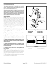
Switch Adjustment
1. Adjust switch to have 1/16 in (1.6mm) clearance be-
tweenswitchandsensingplateontheliftarm.
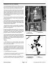
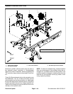
1. Position switch
2. Switch connector
3. Lift arm (#5 shown)
Figure 39
2
1
3
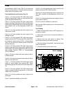
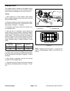
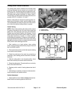
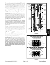
Figure 40
#4 Deck #1 Deck #5 Deck
#7 Deck
(GM4700)
#6 Deck
(GM4700)
#3
Deck
#2
Deck
CUTTING DECK LOCATIONS
Electrical
System