


Groundsmaster 4500--D/4700--DHydraulic S ystem Page 4 -- 130
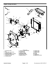
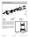
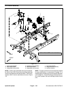
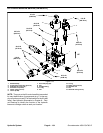
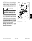
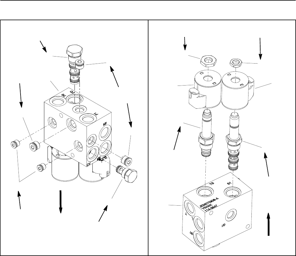
Fan Control Manifold Service
1. Manifold body
2. Zero leak plug (#6) (3 used)
3. Zero leak plug (#4) (2 used)
4. Check valve (port CV)
5. Flow divider cartridge (port FD)
6. Solenoid coil (2 used)
7. Nut
8. Solenoid valve (port S1)
9. Proportional relief cartridge (port TS)
10. Nut
Figure 109
7
4
6
3
2
1
5
9
8
2
2
6
25 ft--lb
(34 N--m)
25 ft--lb
(34 N--m)
20 ft--lb
(27 N--m)
5 ft--lb
(6.8 N--m)
20 ft--lb
(27 N--m)
25 ft--lb
(34 N--m)
25 ft--lb
(34 N--m)
5 ft--lb
(6.8 N--m)
1
10
UP
UP
50 ft--lb
(68 N--m)
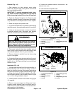
NOTE: The ports on the fan control manifold are
marked for easy identification of components (e.g. ST is
the supply to the steering control valve and FD is the
location of the flow divider cartridge valve). See Hydrau-
lic Schematicsin Chapter 9 -- Foldout Drawings toidenti-
fy the function of the hydraulic lines and cartridge valves
at each port location.
For solenoid and control valve service procedures, see
Control Manifold Cartridge Valve Service in this section.
Refer to Figure 109 for cartridge valve and plug installa-
tion torque.
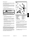
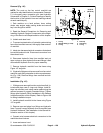
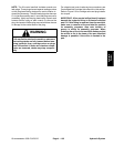
NOTE: The fan control manifold includes several zero
leak plugs. These plugs have a tapered sealing surface
on the plug head that is designed to resist vibration in-
duced plug loosening. The zero leak plugs also have an
O--ring as a secondary seal. If zero leak plug removal is
necessary, lightly rap the plug head using a punch and
hammer before using an allen wrench to remove the
plug: the impact will allow plug removal with less chance
of damage to the socket head of the plug.