


Groundsmaster 4500--D/4700--D Cutting DecksPage 8 -- 19
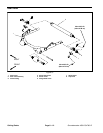
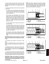
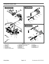
Removal and Installation (Fig. 19)
Each cutting deck is suspended from a carrier frame.
The cutting deck carrier frame is a ttached to the lift arm
and allows the cutting deck to pivot on the lift arm pivot
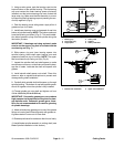
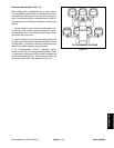
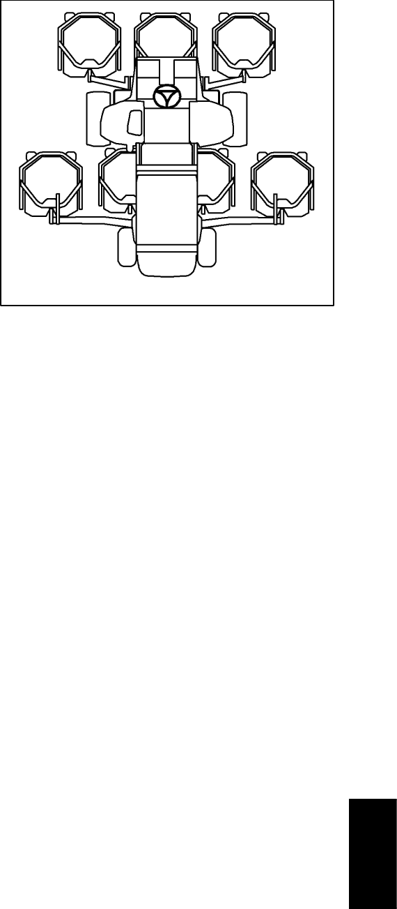
shaft. Cutting deck positions are identified in Figure 20.
Cutting deck carrier frames are secured to lift arms as
follows:
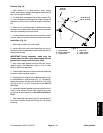
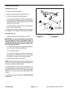
1. Carrier frames for the front three cutting decks (#1,
#4 and #5) have a thrust washer between the carrier
frame and thelift arm. The frameis secured to thelift arm
pivot shaft with a lynch pin.
2. Carrier frames for the center two cutting decks (#2
and #3) have a thrust washer between the carrier frame
and the lift arm. The frame is secured to the lift arm pivot
shaft with a rebound washer and cap screw.
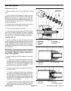
3. On Groundsmaster 4700--D machines, carrier
frames for the rear two cutting decks (#6 and #7) have
a compression spring and thrust washer between the
carrier frame andthe lift arm. The frame issecured tothe
lift arm pivot shaft with a flat washer and lock nut.
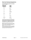
Figure 20
#4 Deck #1 Deck #5 Deck
#7 Deck
(GM4700)
#6 Deck
(GM4700)
#3
Deck
#2
Deck
CUTTING DECK LOCATIONS
Cutting Decks