


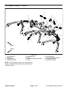
Groundsmaster 4500--D/4700--DHydraulic S ystem Page 4 -- 136
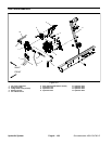
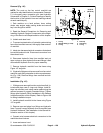
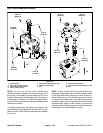
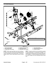
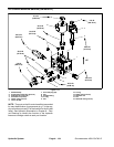
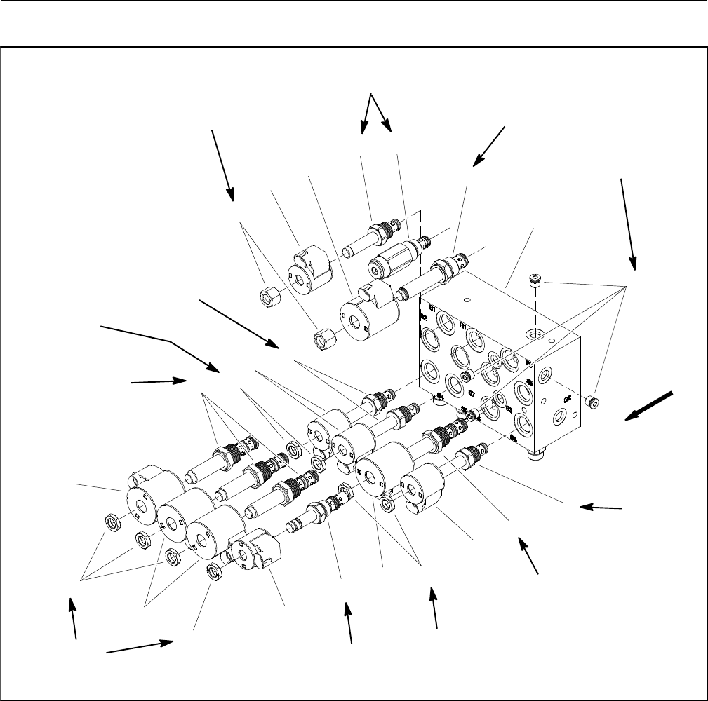
Lift Control Manifold Service (GM 4700--D)
1. Manifold body
2. Nut
3. Zero leak plug (#4)
4. Relief valve (port R1)
5. Proportional relief valve (port TS)
6. Solenoid valve (ports S2, S3, S7, S 8)
7. Solenoid valve (port S1)
8. Solenoid valve (ports S4, S6, S9)
9. Solenoid valve (port S5)
10. Solenoid coil (5 used)
11. Solenoid coil ( 5 used)
12. Nut
Figure 114
7
4
6
10
3
11
12
2
1
5
9
8
6
8
10
10
10
11
11
11
5ft--lb
(6.8 N--m)
20 ft--lb
(27 N--m)
25 ft--lb
(34 N--m)
20 ft--lb
(27 N--m)
25 ft--lb
(34 N--m)
25 ft--lb
(34 N--m)
20 ft--lb
(27 N--m)
20 ft--lb
(27 N--m)
5ft--lb
(6.8 N--m)
12
5ft--lb
(6.8 N--m)
12
12
5ft--lb
(6.8 N--m)
UP
20 ft--lb
(27 N--m)
NOTE: The ports on the lift control manifold are marked
for easy identification of components (e.g. P is the gear
pump connection port and R1 is the relief valve port).
See Hydraulic Schematics in Chapter 9 -- Foldout Draw-
ings toidentify the functionof the hydraulic lines and car-
tridge valves at each port location.