


Groundsmaster 4500--D/4700--D Hydraulic SystemPage 4 -- 23
Raise Cutting Decks: Groundsmaster 4700--D
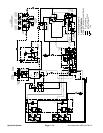
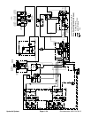
A four section gear pump is coupled to the piston (trac-
tion) pump. The third gear pump section supplies hy-
draulic flow to both the lift control manifold and the
steering control valve. Hydraulic flow from this pump
section is delivered to the circuits through a proportional
flow divider located in the fan control manifold. Maxi-
mum lift/lowercircuit pressure is limitedto 1600PSI (110
bar) by a relief valve (R1) in the lift control manifold. Lift
circuit pressure can be monitored at test fitting G1 in the
lift control manifold.
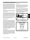
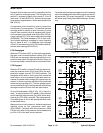
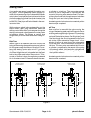
The Groundsmaster 4700--D has three (3) lift switches
to control the cutting decks (Fig. 16). The center switch
is for the five (5) center decks, the left switch controls the
left, rear deck (#6) and the right switch controls the right,
rear deck (#7) (Fig. 17).
When the cutting decks are in a stationary position (not
raising or lowering), lift circuit flow from the third pump
section bypasses the lift cylinders through the lift control
manifold solenoid valve S1 and proportional relief valve
TS which are de--energized. Return flow from the man-
ifold is routed to the oil filter and traction charge circuit.
NOTE: The operator must be in the operator seat in or-
der to raise the cutting decks.
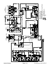
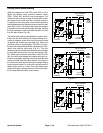
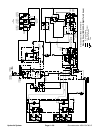
Cutting Deck Raise
To raise the center five (5) cutting decks on the
Groundsmaster 4700--D, the rear of the center console
switch is depressed. The switch acts as an input to the
TEC--5002 controller which then provides an electrical
output to s olenoid valves S1 and S5 in the lift control
manifold. The energized solenoid valves shift to allow a
passage for oil flow to the rod ends of the center five (5)
deck lift cylinders. The oil flow causes the lift cylinders
to retract and raises the center five (5) cutting decks.
The orifice in lift manifold port C2 is bypassed during
deck raising. Two (2) orifices in the junction manifold
control the raising speed of the #4 and #5 decks. The
junction manifold orifice leading to the #1 deck is by-
passed during deck raising.
To raise a side cutting deck on the Groundsmaster
4700--D (deck #6 or #7), the rear of the appropriate con-
sole arm lift switch is depressed. The switch acts as an
input to the TEC--5001 controller which then provides an
electrical output to the appropriate solenoid valves inthe
lift control manifold: S1 and S2 for deck #6 and S1 and
S7 for deck #7. The energized solenoid valves shift to
allow a passage for oil flow to the rod ends of the deck
lift cylinder. The oil flow causes the lift cylinder to retract
and r aises the cutting d e ck. An orifice in the lift manifold
restricts oil flow to the lift cylinder to control deck raising
speed.
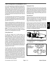
Figure 16
1. Lift switch (#1 to # 5)
2. Lift switch (#6)
3. Lift switch (#7)
1
2
3
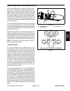
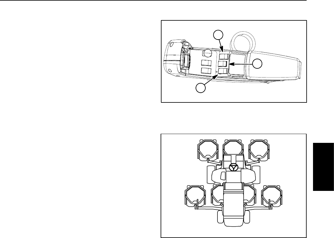
Figure 17
#4 #1 #5
#7#6 #3#2
GM--4700 CUTTING DECK LOCATIONS
Hydraulic
System