


Groundsmaster 4500--D/4700--DHydraulic System Page 4 -- 92
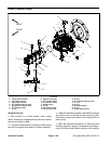
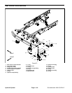
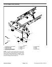
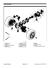
Rear Traction Control Manifold Service
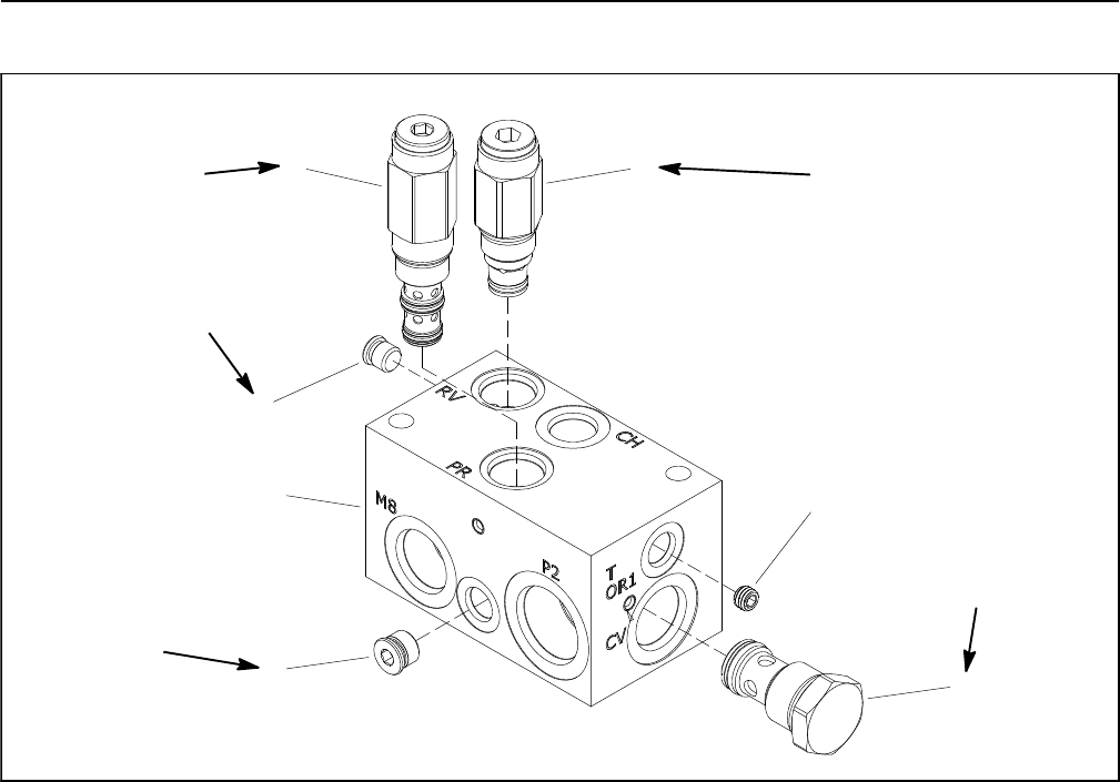
1. Rear traction manifold body
2. Relief valve (port RV)
3. Pressure reducing valve (port PR)
4. #4 zero leak plug with O--ring
5. #6 zero leak plug with O--ring
6. Check valve (port CV)
7. Orifice (0.050) (port OR1)
Figure 74
25 ft--lb
(34 N--m)
35 ft--lb
(47 N--m)
20 ft--lb
(27 N--m)
50 ft--lb
(67 N--m)
1
2
4
3
5
6
7
25 ft--lb
(34 N--m)
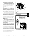
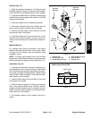
NOTE: The ports on the rear traction manifold are
marked for easy identification of components. Example:
P2 is a piston pump connection port and RV is the loca-
tion for the relief valve (see Hydraulic Schematic in
Chapter 10 -- Foldout Drawings to identify the function
of the hydraulic lines and cartridge valves at each port).
NOTE: The rear traction manifold uses several zero
leak plugs. These plugs have a tapered sealing surface
on the plug head that is designed to resist vibration in-
duced plug loosening. The zero leak plugs also have an
O--ring as a secondary seal. If zero leak plug removal is
necessary, lightly rap the plug head using a punch and
hammer before using an allen wrench to remove the
plug: the impact will allow plug removal with less chance
of damage to the socket head of the plug.
For rear traction manifold cartridge valve service proce-
dures, see Control Manifold Cartridge Valve Service in
this section. Refer to Figure 74 for rear traction manifold
cartridge valve and plug installation torque.
IMPORTANT: A flow control orifice (item 7) is lo-
cated beneath the hydraulic fitting in rear traction
manifold port T/OR1. If the orifice i s removed from
this manifold port, make sure tolabel its position for
assembly purposes. When installing the orifice in
the manifold, make sure that the orifice is properly
tightened in the port.