


Groundsmaster 4500--D/4700--D Hydraulic SystemPage 4 -- 47
NOTE: Thetractionchargecircuitisdesignedtore-
place loss of hydraulic fluid from the closed loop traction
circuit.
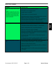
Procedure for Traction Circuit Charge Pressure
Test
CAUTION
Prevent personal injury and/or damage to equip-
ment. Read all WARNINGS, CAUTIONS and Pre-
cautions for Hydraulic Testing at the beginning
of this section.
1. Make sure hydraulic oil is at normal operating tem-
perature by operatingthe machinefor approximately ten
(10) minutes. Make sure the hydraulic reservoir is full.
2. Park machine on a level surface with the cutting
decks lowered and off. Make sure hydraulic oil is at nor-
mal operating temperature, engine is OFF, the parking
brake is engaged and the hydraulic reservoir is full.
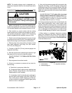
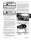
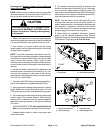
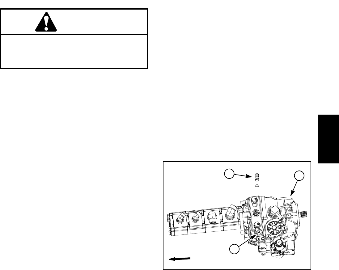
3. Raise hood and locate piston (traction) pump charge
port plug on top ofpump (Fig. 38). Thoroughly pump sur-
faces around plug to prevent system contamination.
4. Remove plug from pump traction charge port and
then install diagnostic test fitting (Toro part number
59--7410) into charge port.
5. Connect a 1000 PSI (70 bar) pressure gauge onto
diagnostic test fitting.
6. Start the engine and increase engine speed to h igh
idle speed with no load on the hydraulic system.
GAUGE READING TO BE 200 to 300 PSI (13.8 to
20.6 bar)
7. Stop engine and record test results.
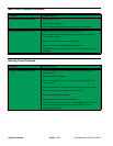
8. If there is no pressure or pressure is low, check for
the following:
A. Restriction in gear pump intake line.
B. Charge relief valve in piston pump is leaking (see
Piston (Traction) Pump Service in the Service and
Repairs section of this chapter).
C. If necessary,check for internal wear or damagein
the third gear pump section (see Gear Pump Flow
Test in this section). NOTE: Steering and lift/lower
circuitswouldalsobeaffectedifthethirdgearpump
section is worn or damaged.
9. Next, with the pressure gauge still connected to the
diagnostic test fitting, monitor the gauge reading while
operating the machine in forward and reverse. Start the
engine and increase engine speed to high idle speed.
Apply the brakes and push the traction pedal forward,
then reverse.
GAUGE R EADING TO BE within 20% of no--load
charge pressure measured in step 4 above (e.g.
if charge pressure in step 6 is 250 PSI (17.2 bar),
charge pressure in forward or reverse should be
from 20 0 to 250 PSI (13.8 to 17.2 bar)
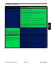
10.If charge pressure is good under no load (step 6), but
drops below specification when under traction load
(step 9), the piston (traction) pump, front wheel motors
and/or rear axle motor should be suspected of wear and
inefficiency.When the pump and/ortraction motor(s)are
worn or damaged, the charge pump is not able to keep
up with internal leakage in traction circuit components.
11.When testing is completed, disconnect pressure
gauge from d iagnostic test fitting. Remove diagnostic
test fitting from piston (traction) pump. Install plug into
piston pump port and torque plug to 32 ft--lb (43 N--m).
Lower and secure hood.
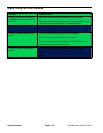
1. Traction pump
2. Traction charge port
3. Diagnostic test fitting
Figure 38
FRONT
2
1
3
Hydraulic
System