


Groundsmaster 4500--D/4700--DHydraulic System Page 4 -- 98
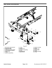
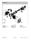
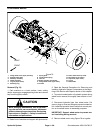
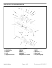
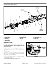
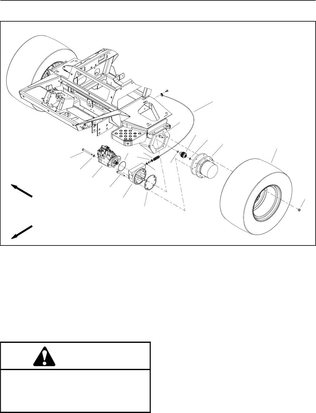
Front Wheel Motors
1. Flange head screw (6 per planetary)
2. Splined brake shaft
3. Planetary assembly
4. Wheel assembly
5. Lug nut (8 per wheel)
6. Retaining ring
7. Spring plate
8. Compression spring
9. Jam nut
10. Brake assembly (LH shown)
11. Flange head screw (4 per brake)
12. Gasket
13. Piston wheel motor (2 used)
14. Flat washer ( 2 per m otor)
15. Cap sc rew (2 per motor)
16. O--ring
17. Brake cable
Figure 79
10
5
6
12
7
8
2
3
14
4
16
9
1
11
15
6
13
17
FRONT
RIGHT
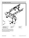
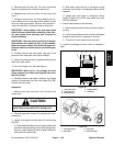
Removal (Fig. 79)
1. Park machine on a level surface, lower cutting
decks, stop engine, engage parking brake and remove
key from the ignition switch.
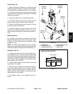
CAUTION
When changing attachments, tires or perform-
ing other service, use correct blocks, hoists and
jacks toraise and support machine.See Jacking
Instructions in Chapter 2 -- Safety for additional
information and precautions.
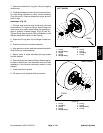
2. Raise front of machine and support with jack stands.
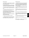
3. Read the General Precautions for Removing and
Installing Hydraulic System Components at the begin-
ning of the Service and Repairs section of this chapter.
4. To prevent contamination of hydraulic system during
wheel motor removal, thoroughly clean exterior of mo-
tor.
5. Disconnect hydraulic lines from wheel motor. Put
caps or plugs on lines and fittings to prevent contamina-
tion. Label the hydraulic lines to show their correct posi-
tion on the wheel motor for assembly purposes.
IMPORTANT: Support w heel motor to prevent mo-
tor from falling during removal.
6. Remove wheel motor using Figure 79 as a guide.