


Groundsmaster 4500--D/4700--D Page 6 -- 19 Axles, Planetaries and Brakes
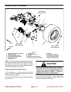
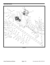
Remove Rear Axle (Fig. 13)
1. Park machine on a level surface, lower cutting
decks, stop engine, engage parking brake and remove
key from the ignition switch.
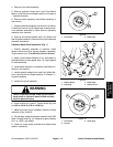
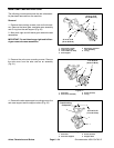
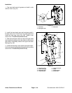
2. Drain oil from rear axle and rear axle gearbox (Figs.
14 and 15).
CAUTION
When changing attachments, tires or perform -
ing other service, use correct jacks, hoists and
jack stands to raise and support machine. See
Jacking Instructions in Chapter 1 -- Safety for
additional information and precautions.
3. Chock front wheels and jack up rear of machine (see
Jacking Instructions in Chapter 1 -- Safety). Support ma-
chine with appropriate jack stands.
4. Remove both wheel assemblies from rear axle.
5. Remove hydraulic motor from axle assembly (see
Rear Axle Motor in the Service and Repairs section of
Chapter 4 -- Hydraulic System).
6. Remove hydraulic hoses from steering cylinder. Put
caps or plugs on hoses and cylinder fittings to prevent
contamination.
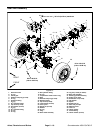
7. Remove lock nut (item 39) and thrust washer (item
40) from rear axle pivot pin.
8. Support rear axle to prevent it from falling. Remove
pivot pin from frame and rear axle. Lower rear axle from
machine. Note location of thrust washer (item 42) on
both ends of axle mounting boss.
9. If needed for further axle disassembly,remove steer-
ingcylinderfromaxle(seeSteeringCylinderintheSer-
vice and Repairs section of Chapter 4 -- Hydraulic
System).
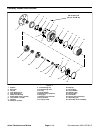
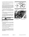
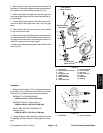
10.If required, remove tie rod ends from steering arms
on rear axle (Fig. 16). Remove the cotter pins and castle
nuts from the tie rod ball joints. Use a ball joint fork and
remove the tie rod ends from the axle steering arms.
11.Clean the rear axle pivot pin and pivot bushings. In-
spect the pinand bushingsfor wear ordamage. Replace
components as necessary.
Install Rear Axle (Fig. 13)
1. If removed, install steering cylinder to axle assembly
(see Steering Cylinder in the Service and Repairs sec-
tion of Chapter 4 -- Hydraulic System).
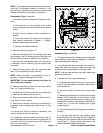
1. Outside plug (2 used) 2. Center axle drain plug
Figure 14
2
1
1. Gearbox drain plug 2. Gearbox fill plug
Figure 15
1
2
1. T ie rod
2. Dust cover
3. Cotter pin
4. Ca stle nut
5. Tie rod end
6. Steering arm (LH)
Figure 16
1
2
3
5
4
6
Axles, Planetaries
and Brakes