


Groundsmaster 4500--D/4700--DHydraulic S ystem Page 4 -- 106
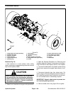
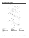
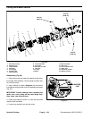
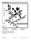
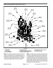
Assembly (Fig. 86)
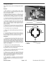
NOTE: When assembling the motor, check the marker
line on each part to make sure the parts are properly
aligned during assembly.
1. Lubricate O--rings, pressure seals, back--up gaskets
and wear plate grooves with a thin coat of petroleum jel-
ly. Lubricate all other internal parts freely with clean hy-
draulic oil.
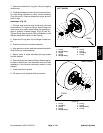
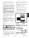
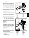
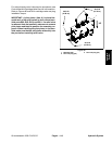
2. Install new seals into front flange (Fig. 88):
A. Press shaft seal into front flange until it reaches
the bottom of the bore.
B. Install flange washer into front flange and then
install retaining ring into the groove of the front
flange.
C. Install new dust seals into front flange.
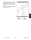
3. Place front flange, seal side down, on a flat surface.
4. Install the pressure seals, flat side outward, into the
grooves in the wear plates. Follow by carefully placing
thebackupgaskets,flatsideoutward,betweenthe
pressure seals and the grooves in the wear plate.
5. Applya light coating of petroleum jelly to theexposed
side of the front flange.
6. Lubricate the drivegear shaft with clean hydraulic oil.
Insert the drive end of the drive shaft through the wear
plate with the pressure seal side down andthe open side
of the pressure seal pointing to the inlet side of the mo-
tor. Carefully install shaft into front flange.
7. Lubricate the idler gear shaft with clean hydraulic oil.
Install idler gear shaft into the remaining position in the
front wear plate. Apply a lig ht coating of clean hydraulic
oil to gear faces.
8. Install rear wear plate with pressure seal side upand
open side of the pressure seal pointing to the inlet side
of the motor.
9. Apply a light coating of petroleum jelly to new O--
rings and O--ring grooves in the body. Install new O--
rings to the body.
10.Install locating dowels in body. Align marker line on
the body and front flange.
IMPORTANT: Do not dislodge seals during installa-
tion.
11.Gently slide the body onto the assembly. Firm hand
pressure should be sufficient to engage the dowels.
12.Check to make sure that the surface of the rear wear
plate is slightly below the face of the body. If the wear
plate is not below the body, check assembly for a shifted
pressure seal, backup gasket or O--ring. Correct before
proceeding.
13.Apply a lightcoating of petroleum jellyto the exposed
side of the rear cover.
14.Place rear cover on assembly using marker line for
proper location. Firm hand pressure should be sufficient
to engage the dowel pins.
15.Install the four (4) cap screws with washers and hand
tighten screws.
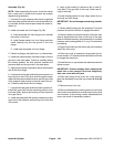
IMPORTANT: Prevent damage when clamping the
motor into a vise; clamp on the front flange only.
Also, use a vise with soft jaws.
16.Place front flange of the motor into a vise with soft
jaws and alternately torque the cap screws 33 ft--lb (45
N--m).
17.Remove motor from vise.
18.Place a small amount of clean hydraulic oil inthe inlet
of the motorand rotatethe driveshaft awayfrom theinlet
one revolution. If any binding is noted, disassemble the
motor and check for assembly problems.