Groundsmaster 4500--D/4700--DHydraulic System Page 4 -- 70
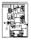
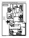
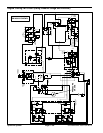
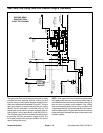
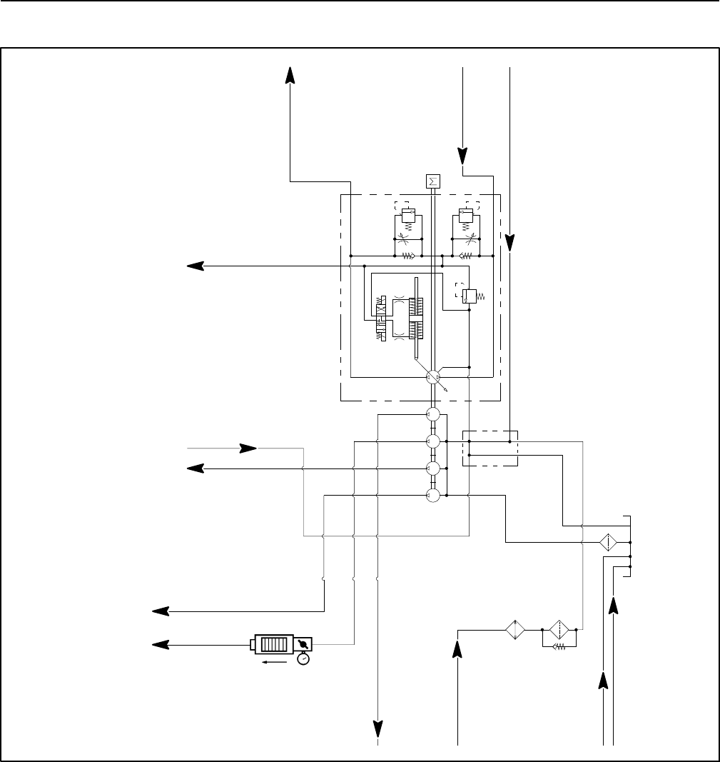
Gear Pump Flow (Using Tester with Pressure Gauge & Flow Meter)
SECOND GEAR
PUMP SECTION
TESTER
4350 PSI
250 PSI
5000 PSI
EU -- 2600 /1200 RPM
0.56
CID
0.56
CID
1.03
CID
1.03
CID
2.75
CID
50
PSI
ENGINE
T4 -- 2700 /1200 RPM
PISTON
PUMP
FROM REAR
TRACTION VALVE
REAR DECK & COOLING FAN
MOTOR CASE DRAIN
CASE DRAIN
FRONT DECKMOTOR
FROM STEERING
TRACTION
CONTROLVALVE
FLOW
MANIFOLD PORT P1
TO F AN CONTROL
TODECK CONTROL
MANIFOLD PORT P1
CHARGE
CIRCUIT
FROM WHEEL MOTOR CASE DRAIN
CIRCUITFLOW
TODECK CONTROL
MANIFOLD PORT P2
MANIFOLD PORT P2
TO FAN CONTROL
FROM DECKCONTROL
MANIFOLD PORTT1
FLOW TEST SHOWN
The gear pump flow test should be performed to make
sure that the mow, steering, lift/lower, cooling fan and
traction charge circuits have adequate hydraulic flow.
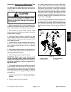
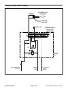
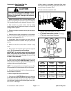
Gear pump sections are illustrated in Figure 57. The first
gear pump section provides hydraulic flow for cutting
decks 2, 3 and 5 (also deck 7 on the GM 4700--D). The
second gear pump section provides hydraulic flow for
cutting decks 1 and 4 (also deck 6 on the GM 4700--D).
The third gear pump section provides hydraulic flow for
the steering, lift/lower and traction charge circuits. The
fourth gear pump section provides hydraulic flow for the
engine cooling fan circuit.
NOTE: Overaperiodoftime,thegearsandwearplates
in the gear pump can wear. A worn pump will by pass oil
and make the pump less efficient. Eventually,enough oil
loss will occur to cause circuit problems (e.g. cutting
deck motors stalling under heavy cutting conditions, lift
or steering problems). Continued operation with a worn,
inefficient gear pump can generate excessive heat and
cause damage to the seals and other components in the
hydraulic system.


