


Groundsmaster 4500--D/4700--DPage 6 -- 20Axles, Planetaries and Brakes
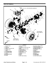
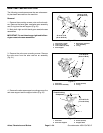
2. If removed, install the tie rod to rear axle (Fig. 16).
Tighten ball joint castle nuts and i nstall new cotter pins.
3. Support axle under machine with a jack. Position
axle assembly to rear frame mount.
4. Install rear axle pivot pin t o secure axle to frame.
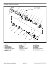
Make sure to install thrust washer (item 42) between
axle pivot and frame on both ends of the pivot. With
thrust washers installed, there should be from 0.002 to
0.020 inch (0.05 to 0.51 mm) clearance between rear
frame mount and axle mounting boss. Add additional
thrust washers if needed to adjust clearance.
5. Install thrust washer (item 40) and lock nut (item 39)
onto axle pivot pin. L ock nut should be tightened enough
to allow pivot pin to rotate (70 ft--lb (94 N--m) maxi-
mum).
6. Install hydraulic motor to axle assembly (see Rear
Axle Motor in the Service and Repairs section of Chap-
ter 4 -- Hydraulic System).
7. Remove caps and plugs from hydraulic hoses and
steering cylinder fittings. Secure hydraulic hoses to
steering cylinder (see Hydraulic Hose and Tube Installa-
tion in the General Information section of Chapter 4 --
Hydraulic System).
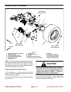
Failure to maintain proper wheel lug nut torque
could result in failure or loss of wheel and may
result in personal injury.
WARNING
8. Install wheel assemblies torear axle. Lower machine
to ground. Torque wheel lug nuts from 85 to 100 ft--lb
(116 to 135 N--m).
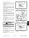
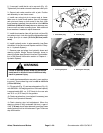
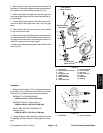
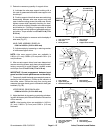
9. Fill rear axle (Fig. 17) and rear axle gearbox (Fig. 15)
with SAE 85W--140 weight gear lube. Lubricant capacity
is approximately 80 fl. oz. (2.37 liters) for the rear axle
and 16 fl. oz. (0.47 liters) for the gearbox.
10.Check rear wheel toe--in and adjust if necessary (see
Traction Unit Operator’s Manual).
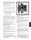
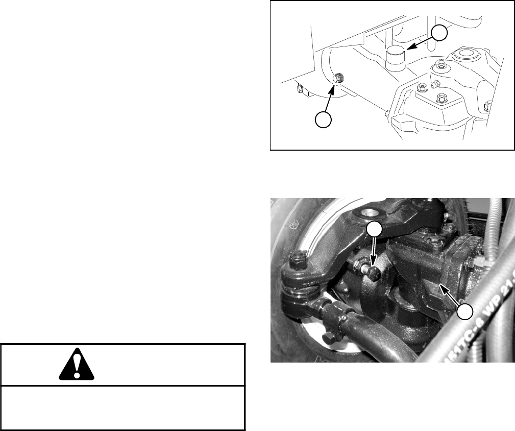
11.Check steering stop bolt adjustment. When the
steering cylinder is fully contracted (left turn), a gap of
1/16” (1.6 mm) should exist between bevel gear case
casting and stop bolt on left axle case. Figure 18 shows
stop bolt location.
1. Axle check plug 2. Axle fill plug
Figure 17
2
1
1. Steering stop bolt 2. Bevel gear case (LH)
Figure 18
2
1