


Groundsmaster 4500--D/4700--D Hydraulic SystemPage 4 -- 91
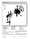
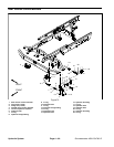
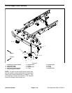
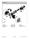
Removal (Fig. 73)
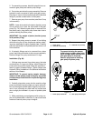
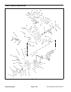
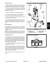
NOTE: The ports on the rear traction control manifold
are marked for easy identification of components. Refer
to the Hydraulic Schematics in Chapter 9 -- Foldout
Drawings to identify the function of the hydraulic lines
and cartridge valves at each port.
1. Read the General Precautions for Removing and
Installing Hydraulic System Components at the begin-
ning of the Service and Repairs section of this chapter.
2. To prevent contamination of hydraulic system during
manifold removal, thoroughly clean exterior of manifold.
3. Label all hydraulic lines for assembly purposes.
4. Disconnect hydraulic lines from manifold and put
caps or plugs on open hydraulic lines and fittings.
5. Remove rear traction control manifold from the
frame using Figure 73 as guide.
6. If hydraulic fittings are to be removed from control
manifold, mark fitting orientation to allow correct as-
sembly. Remove fittings from manifold and discard O--
rings.
Installation (Fig. 73)
1. If fittings were removed from control manifold, lubri-
cate and place new O--rings onto fittings. Install fittings
into manifold ports using marks made during the remov-
al process to properly orientate fittings. Tighten f ittings
(see Hydraulic Fitting Installation in the General Infor-
mation section of this chapter).
2. Install rear traction control manifold to the frame us-
ing Figure 73 as guide.
3. Remove caps and plugs from fittings and hoses. Us-
ing labels placed during manifold removal, properlycon -
nect hydraulic linesto manifold (see Hydraulic Hose and
Tube Installation in the General Information section of
this chapter).
4. Fill hydraulic reservoir with hydraulic fluid as re-
quired.
Hydraulic
System