


Groundsmaster 4500--D/4700--DHydraulic System Page 4 -- 110
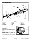
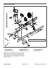
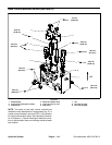
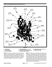
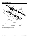
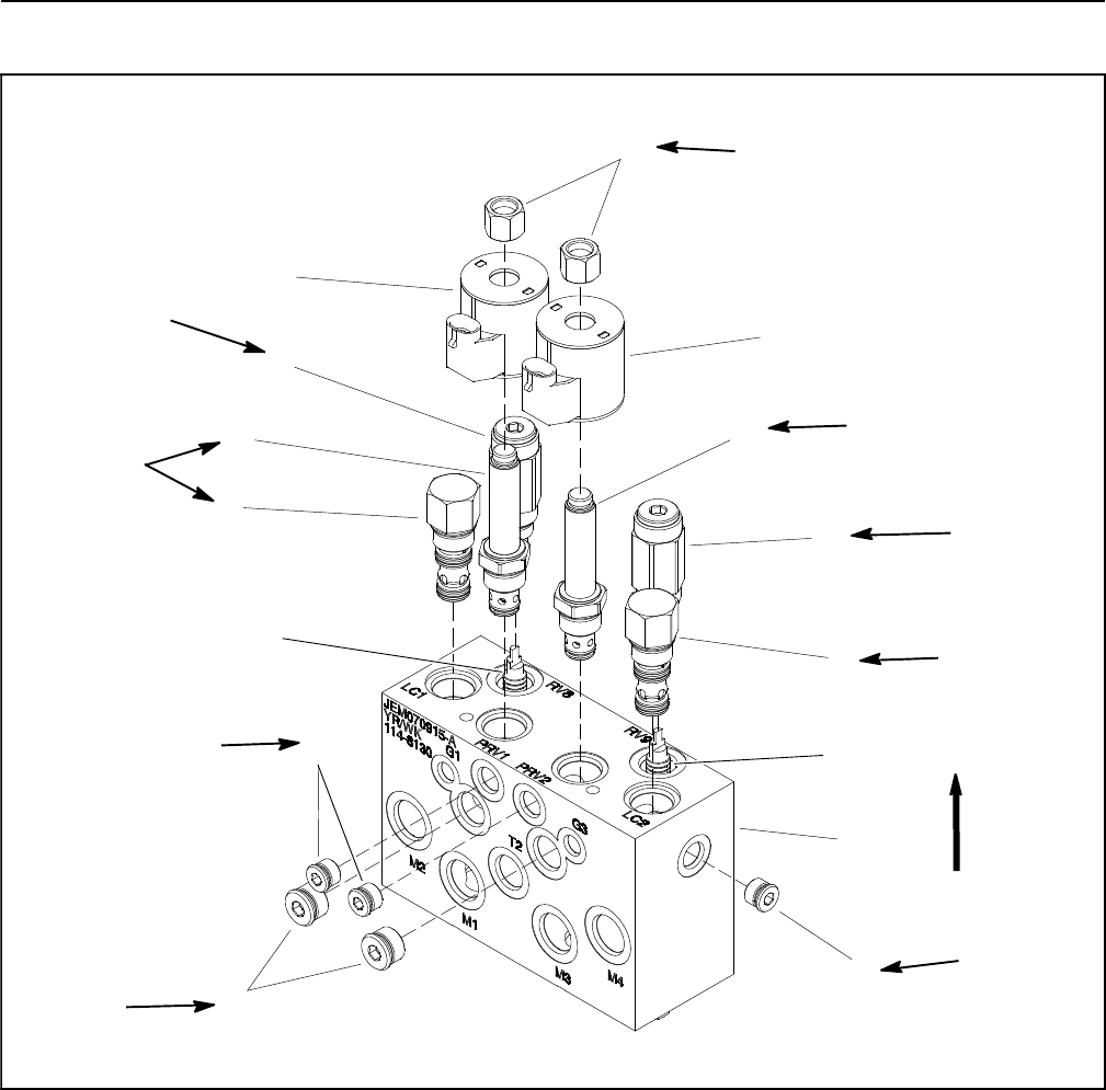
Deck Control Manifold Service (GM 4500--D)
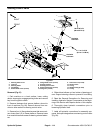
1. Manifold body
2. Proportional relief (PRV1 & PRV2)
3. Solenoid coil
4. Relief valve (RV8 & RV9)
5. Logic valve (LC1 & LC2)
6. Pilot piston
7. Nut
8. Zero leak plug (#6)
9. Zero leak plug (#8)
Figure 93
1
3
4
5
6
7
9
8
2
3
2
4
5
6
8
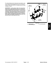
5ft--lb
(6.8 N--m)
25 ft--lb
(34 N--m)
20 ft--lb
(27 N--m)
25 ft--lb
(34 N--m)
25 ft--lb
(34 N--m)
25 ft--lb
(34 N--m)
25 ft--lb
(34 N--m)
20 ft--lb
(27 N--m)
UP
50 ft--lb
(68 N--m)
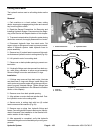
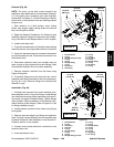
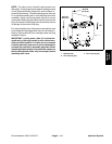
NOTE: The ports on the deck control manifold are
marked for easy identification of components (e.g. P1 is
a gear pump connection port and PRV1 is the location
for a proportional relief valve). See Hydraulic Schemat-
ics in Chapter 9 -- Foldout Drawings to identify the func-
tion of the hydraulic lines and cartridge valves at each
port location.