


Groundsmaster 4500--D/4700--DHydraulic S ystem Page 4 -- 132
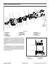
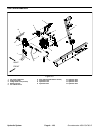
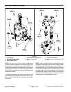
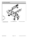
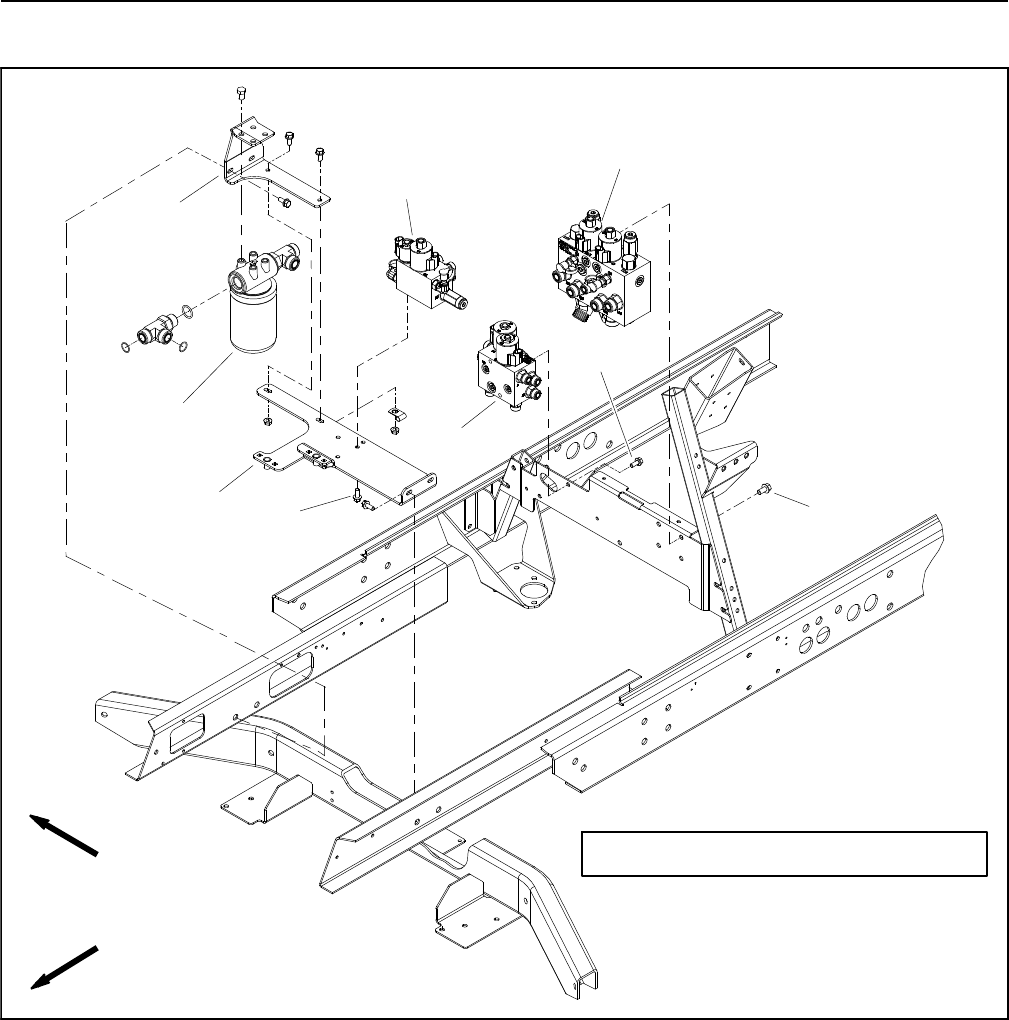
Lift Control M anifold
1. Deck control manifold
2. Filter mount bracket
3. Flange head screw (2 used)
4. Hydraulic oil filter assembly
5. Valve mount bracket
6. Flange head screw (2 used)
7. Lift control manifold
8. Flange head screw (2 used)
9. Fan drive manifold
Figure 110
FRONT
RIGHT
GROUNDSMASTER 4500--D SHOWN
1
7
8
4
6
3
2
5
9
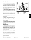
NOTE: The lift control manifolds used on Groundsmas-
ter 4500--D and 4700 --D machines are different but they
mount to the machine in the same location. TheGround-
smaster 4500--D control manifolds are shown in Figure
110.
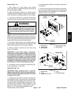
NOTE: The ports on thelift control manifold are marked
for easy identification of components. Example: P1 is
the gear pump connection port (see Hydraulic Schemat-
ics in Chapter 9 -- Foldout Drawings to identify the func-
tion of the hydraulic lines and cartridge valves at each
port).