


Greensmaster 3320/3420 Hydraulic SystemPage 5 -- 17
Raise Cutting Units
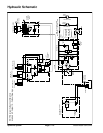
The gear pumpis directlycoupledto thepiston (traction)
pump. The gear pump supplies hydraulic flow for the
steering circuit (priority flow), for raising and lowering
the cutting units and for the traction charge circuit. The
gear pump takes itssuction fromthe hydraulicreservoir.
Maximum circuit pressure of1160 PSI (80 bar) is limited
by the relief valve located in the power steering valve.
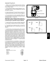
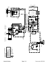
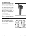
The lift control manifold includes four (4) electrically op-
eratedsolenoidvalves. Solenoidvalve S1causescircuit
flow to by--pass the lift cylinders when de--energized
and directs f low to the cylinders when energized. Direc-
tional solenoid valve S2 is used to direct oil flow to raise
the cutting units when de--energized and lower them
when energized. When energized,solenoid valve S3al-
lows hydraulic flow to and from the front cutting unit lift
cylinders (#2 and #3) and prevents oil passage to and
from the lift cylinders when de--energized. When ener-
gized, solenoid valve S4 a llows hydraulic flow to and
fromthe center cutting unit lift cylinder( #1) andprevents
oil p assage to and from the lift cylinder when de--ener-
gized.
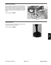
Theconsolearmjoystickisusedtoraiseandlowerthe
cutting units. The joystick acts as an input to the TEC
controller to send electrical outputs to appropriate lift
control manifold solenoid coils in order to raise or lower
the cutting units.
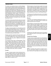
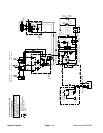
While operating the machine during conditions of not
raising or lowering the cutting units (joystick in the neu-
tral (center) position), all of the lift manifold solenoid
valves (S1,S2, S3and S4)arede--energized. Flowfrom
the gear pump is directed through the power steering
valve, de--energized solenoid valve S1 in the lift control
manifold, oil filter and to the traction charge circuit. Flow
inexcess of chargecircuit needsthen returnsto thegear
pump input.
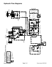
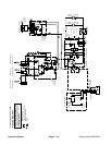
Raise Cutting Units
Whenthejoystickismovedto theraiseposition,theToro
Electronic Controller (TEC) energizes lift control man-
ifold solenoid valves S1, S3 and S4 for approximately
three (3) seconds. This time frame ensures that the cut-
ting units will be fully raised. The controller provides a
shortdelay inenergizing solenoidvalve S4whichdelays
the raising of the center cutting unit (#1).
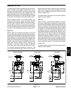
Energized lift manifold solenoids S1, S3 (front lift cylin-
ders) and S4 (center lift cylinder) direct circuit flow to-
ward the lift cylinders in the correct direction to r aise the
cutting units. The front lift cylinders retract to raise the
cuttingunits whilethe center liftcylinder extends toraise
the cutting unit. Hydraulic pressure against the lift cylin-
der pistons moves their shafts causing the cutting units
to raise. At the same time, the lift cylinder pistons push
the hydraulic fluid out of the cylinders to de--energized
solenoid valve S2. Return flow continues to the oil filter
and then to the traction charge circuit.
A 0.037 orifice (OR1) controls raising speed for the cen-
tercutting unit(#1). Flow tothefront liftcylinders(cutting
units #2 and#3) bypasses the lift manifold orifices (OR2
and OR3) when the front cutting units are being raised.
When the lift control manifold solenoid valves are de--
energized by the TEC controller, spring action returns
the valves to their original position stopping lift cylinder
movement. The lift cylinder position is locked in place
since there is no complete circuit of flow to and from the
lift cylinders. Hydraulic flow by--passes the lift cylinders
andisroutedtotheoilfilterandchargecircuit.
NOTE: The raise function will not be allowed by the
TEC controller when the machine is in the backlap op-
eration with c utting reels engaged.
Hydraulic
System