


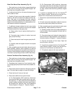
Greensmaster 3320/3420 Page 7 -- 15 Chassis
4. Loosen, but do not remove, rear wheel lug nuts.
5. Jack up rear of machine and support machine with
jack stands (see Jacking Instructions in Chapter 1 --
Safety).
6. Remove rear wheel assembly (see Wheel Removal
in this section).
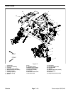
7. Remove two (2) jam nuts that secure steering cylin-
der rod end to the rear steering fork. Separate steering
cylinder rod end f rom the steering fork.
8. Ifmachineis equipped withoptional3WDkit,remove
rear wheel motor from rear steering fork (see Rear
Wheel Motor (Optional 3WD) Removal in the Service
and Repairs section of Chapter 5 -- Hydraulic System).
Carefully, position wheel motor assembly away from
steering fork taking care to not damage hydraulic lines.
9. Support r ear steering f ork assembly to prevent it
from falling.
CAUTION
Support rear steering fork assembly when re-
moving it to prevent it from falling and causing
personalinjury. Assemblyweighsapproximately
25 pounds (11 kg).
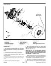
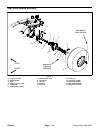
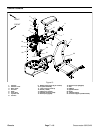
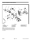
10.Remove cotterpin (item29) andslotted hexnut(item
28) that secure the steering fork spindle into the frame
tube. Slide the rear steering fork assembly out of the
frame. Locate and retrieve steering washer (item 27)
and both bearing cones (item 25).
11.Clean thebearingcones andmake surethebearings
arein good condition.Clean theinsideofthe frametube.
Check the bearing cups for wear, pitting or o ther dam-
age. Replace worn or damaged parts.
12.If necessary, remove wheel spindle assembly from
rear steering fork. Cut--outs in wheel hub will allow ac-
cess to cap screws that secure spindle assembly to
steering fork.
13.Thoroughly clean the steering fork spindle. Inspect
the spindle for wear and replace steering spindle (item
19) if spindle is worn or damaged.
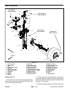
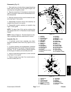
Installation (Fig. 12)
1. If bearing cups were removed from the frame tube,
press new cups into the tube until they seat against the
shoulder of the frame.
2. Apply a light coating of grease to steering fork
spindle.
3. Pack both bearing cones with grease. Install one
bearing onto the steering spindle.
4. Install steering fork assembly into frame:
A. Insert steering fork spindle up through frame
tube.
B. Hold thesteering fork in place.Install the steering
washer and upper bearing cone onto the spindle.
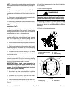
C. Secure steering fork in frame with slotted hex nut
(item 28). Torque nut from 180 to 216 ft--lb (244 to
292 N--m) so that slot in nut aligns with hole in shaft.
D. Install cotter pin.
E. Remove plug (item 30) from back of frame tube
and temporarily install grease fitting (Toro part
#302--5 or equivalent). Fill frame tube with grease
until grease is seen exiting at both ends of the tube.
Wipe up excess grease. Remove grease fitting and
reinstall plug in f rame.
5. If machine is equipped with optional 3WD kit, install
rear wheel motor to rear steering fork (see Rear Wheel
Motor(Optional3WD) Installationin theService andRe-
pairs section of Chapter 5 -- Hydraulic System).
6. If wheel spindle assembly was removed from rear
steering fork, secure spindle assembly to steering fork.
Cut--outs in wheel hub will allow access to cap screws
that secure spindle assembly to steering fork.
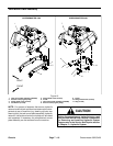
7. Insert the steering cylinder rod end into the rear
steering fork.
8. Secure steering cylinder tosteeringforkwithtwo(2)
jam nuts (item 16). Install first jam nut and torque from
60 to 80 ft--lb (82 to 108 N--m). Then, while holding first
jam nut with wrench, tighten second jam nut and torque
from 60 to 80 ft--lb (82 to 108 N--m).
9. Install rear wheel assembly (see Wheel Installation
in this section).
Failure to maintain proper wheel lug nut torque
could resultin failure orloss ofwheel and mayre-
sult in personal injury.
WARNING
10.Lower machine to ground and make sure that lug
nuts are torqued evenly in a crossing pattern from 65 to
85 ft--lb (89 to 115 N--m).
11.Install tank mount plate assembly to machine (see
Tank Mount Plate Assembly in this section).
Chassis