


Greensmaster 3320/3420Page 6 -- 58Electrical System
Hydraulic Solenoid Valve Coils
The Greensmaster hydraulic control manifolds use sev-
eral hydraulic solenoid valve coils for system control.
The lift manifold includes four (4) solenoid valves. On
machines equipped with the optional Turf Guardian
TM
Leak Detector, the leak detector manifold includes a
single solenoid valve.When the solenoid coils are ener-
gized, hydraulic valve shift occurs to control hydraulic
circuit flow. Testing of the coils can be done with the coil
installed on the hydraulic valve.
Testing
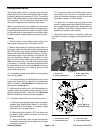
NOTE: Before disconnecting and testing solenoid
valvecoils, testthe TECcontrolleroutputswith theHand
HeldDiagnostic Display(see Hand Held Diagnostic Dis-
play in the Troubleshooting section of this chapter) or
InfoCenter Display (see InfoCenter Display in this
chapter). If the Diagnostic or InfoCenter Display verifies
that the TEC outputs are functioning correctly, consider
that a problem with the solenoid valve coil or circuit wir-
ing may exist. An open or shorted controller output (e.g.
a failed solenoid valve coil, an unplugged connector or
a broken wire) cannot be detected with the Diagnostic
or InfoCenter Display. Conversely, if the Diagnostic or
InfoCenter Display verifies thatthe TEC outputs are not
functioning correctly, consider that a problem with con-
troller inputs, controller fuses or the TEC controller may
exist.
1. Park machine on level surface, lower cutting units,
stop engine, apply parking brake and remove key from
ignition switch.
2. Determine solenoid coil(s) that are to be tested and
locate coil on correct hydraulic manifold:
A. Remove right side cover next to operator seat to
allow access to lift control manifold.
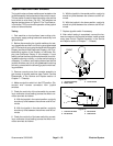
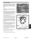
B. To gain access to leak detector manifold, see
Leak Detector Solenoid Valve Assembly in the Ser-
vice and Repairs section of Chapter 5 -- Hydraulic
System.
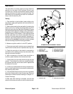
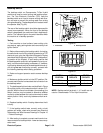
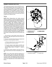
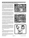
3. Disconnect harness electrical connector from hy-
draulic solenoid valve coil that is to be tested (Fig. 72 or
73).
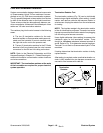
NOTE: Prior to taking small resistance readings with a
digital multimeter, short the meter test leads together.
The metermay displaya small resistance value (usually
0.5 ohms or less). This resistance is due to the internal
resistance of the meter and test leads. Subtract this val-
ue from the measured value of the solenoid coil being
testing.
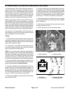
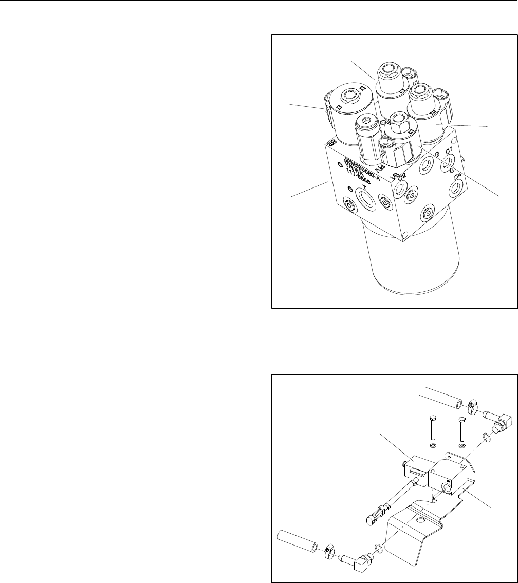
1. Hydraulic lift manifold
2. Solenoid valve S1
3. Solenoid valve S2
4. Solenoid valve S3
5. Solenoid valve S4
Figure 72
2
4
5
3
1
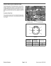
1. Leak detector manifold 2. Solenoid valve
Figure 73
2
1