


Greensmaster 3320/3420Hydraulic System Page 5 -- 64
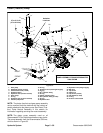
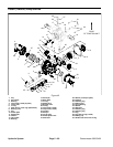
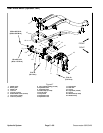
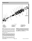
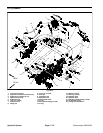
Front Wheel Motors
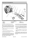
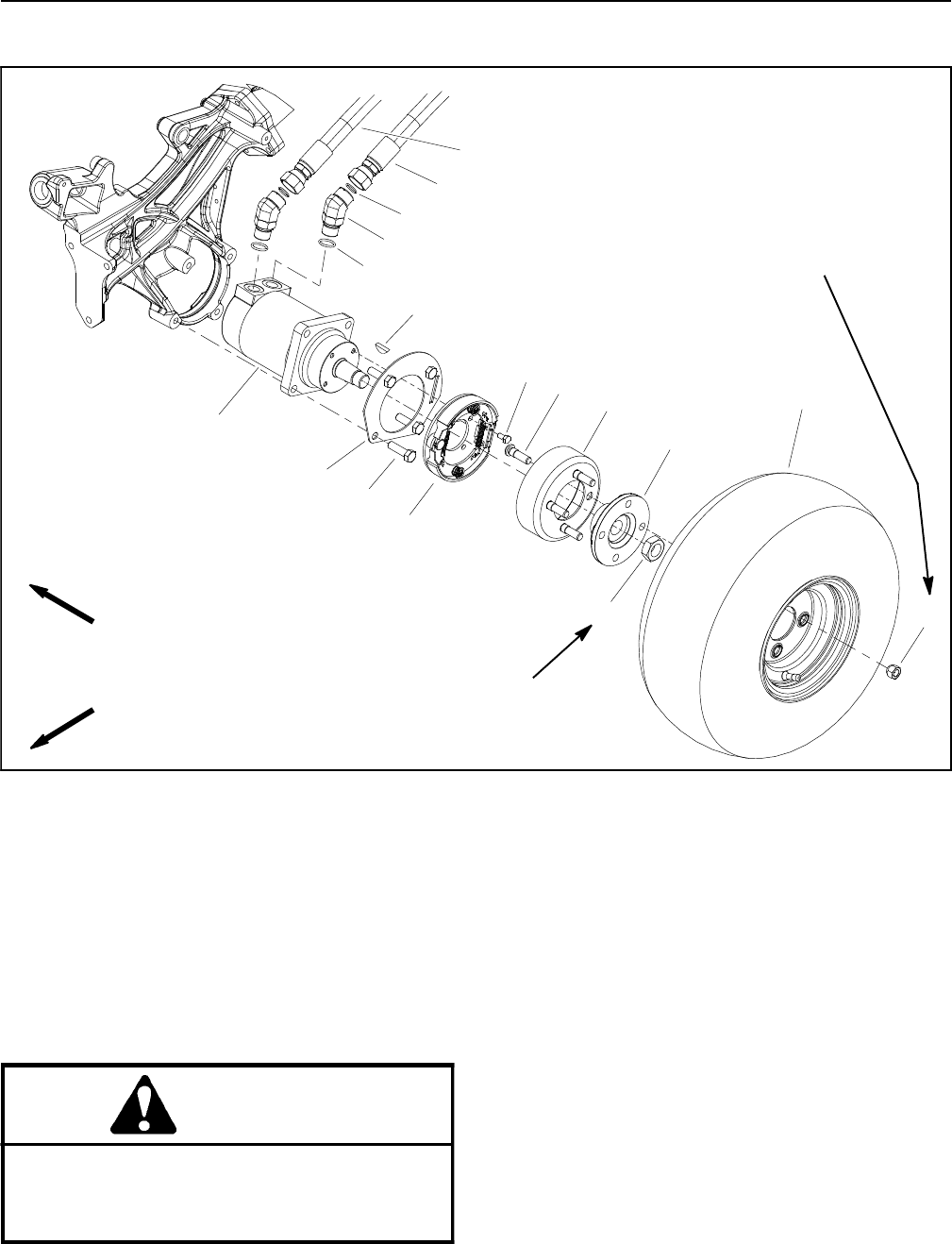
Figure 45
1. Wheel assembly
2. Wheel hub
3. Brake drum
4. Wheel stud (4 per wheel)
5. Brake assembly (LH shown)
6. Cap screw (4 per brake)
7. Lock nut
8. Cap screw (4 per motor)
9. Lug nut (4 per wheel)
10. Brake lever tab
11. Hydraulic motor (LH shown)
12. Woodruff key
13. Hydraulic hose
14. Hydraulic hose
15. O--ring
16. 45
o
hydraulic fitting (2 per motor)
17. O--ring
FRONT
RIGHT
250 to 400 ft--lb
(339 to 540 N--m)
65 to 85 ft--lb
(89 to 115 N--m)
7
10
5
11
1
9
6
8
2
4
3
12
13
14
15
16
17
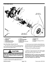
Front Wheel Motor Removal (Fig. 45)
1. Parkmachine ona levelsurface, engagethe parking
brake, lower the cutting units and stop the engine. Re-
move key from the ignition switch.
CAUTION
Before continuing further, read and become fa-
miliar with General Precautions for Removing
and Installing Hydraulic System Components in
this section.
2. Loosen, but donot remove, lugnuts (item9) andlock
nut (item 7). Loosen lock nut at least two (2) turns.
3. Chockfront andrear ofwheels not beinglifted topre-
vent the machine from moving. Lift front wheel off the
ground using a jack and place appropriate jack stands
beneath the frame to support the machine.
4. Remove lug nuts and wheel assembly.
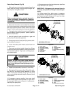
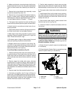
5. Remove e--ring and clevis pin that secure brake
cable clevis to brake actuator lever (Fig. 46). Position
brake cable clevis away from actuator lever.
IMPORTANT: DO NOT hit brake drum assembly,
wheel hub pulleror wheelmotor with ahammer dur-
ing wheel hub removal or i nstallation. Hammering
may cause damage to the wheel motor.