


Greensmaster 3320/3420 Page 6 -- 13 Electrical System
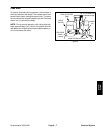
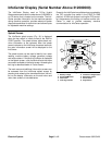
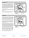
Main Information Screen
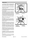
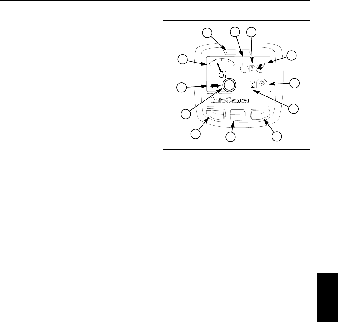
The InfoCenter main information screen (Fig. 17) is dis-
played afterthe initialsplash screen has beendisplayed
for several seconds. During normal machine o peration,
the main information screen provides machine informa-
tion for the operator.
The main informationscreen can be usedto monitor en-
gine coolant temperature, engine RPM, generator volt-
age, PTO speed and hour meter reading. The screen
will also identify if the parking brake is applied.
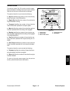
The position of the functional control lever on the con-
sole will be identified on the main information screen as
follows:
D The letter N will be displayed on the InfoCenter
when the functional control lever is in the neutral
position.
D The rabbit icon will be displayed on the Info-
Center when the functional control lever is in the
transport position.
D The turtle icon will be displayed on the Info-
Center when the functional control lever is in the
mow position.
The main information screen will include three (3) ar-
rows to the right of the coolant temperature whenever
the cutting units are either raising (up arrows) or lower-
ing (down arrows).
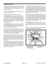
If an electrical machine fault occurs during machine op-
eration, the InfoCenter fault indicator will blink to notify
the operator. Also, the fault log indicator on the Info-
Center screen will be displayed t o notify the operator
thatrecent machinefaultshave occurred.Accessingthe
fault log is described below in Faults Screen.
The main menu and additional information screens can
be accessed from the InfoCenter main information
screen by pressing and releasing the menu/backbutton
(left button) on the display. Information on the main
menu and menu item screens is included below.
1. Coolant temperature
2. Func tional control status
3. Parking brake applied
4. Hour meter
5. PTO speed
6. Generator voltage/status
7. Fault log indicator
8. Engine RPM/status
9. Fault indicator
10. Menu/back button
11. Down button
12. Right button
Figure 17
1
2
6
10
11
12
2600 52.2V
1600
248.6
n/min
n/min
140
180
220
P
8
7
5
4
3
9
Electrical
System