


Greensmaster 3320/3420 Hydraulic SystemPage 5 -- 81
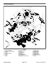
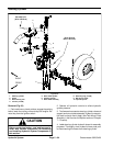
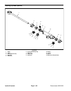
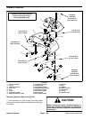
Removal (Fig. 53)
1. Parkmachine on alevel surface,engage theparking
brake, lower the cutting units and stop the engine. Re-
move key from the ignition switch.
CAUTION
Before continuing further, read and become fa-
miliar with General Precautions for Removing
and Installing Hydraulic System Components in
this section.
2. Operate a ll hydraulic controls to relieve hydraulic
system pressure.
3. Remove steering wheel from power steering valve:
A. Remove screw and steering wheel cap from
steering wheel.
B. Remove hex nut and flat washer that secure
steering wheel to power steering valve shaft.
C.Useasuitablepullertoremovesteeringwheel
from power steering valve.
4. Read the General Precautions for Removing and
Installing Hydraulic System Components at the begin-
ning of the Service and Repairs section of this chapter.
5. Loosen and remove four (4) flange head screws that
secure power steering valve to steering mount.
6. Lowerpower steering valve (with hydraulic hoses at-
tached) from steering mount.
7. Label all hydraulic hoses connected to the power
steeringvalvefor assemblypurposes.Thoroughlyclean
hydraulic hose ends.
8. Disconnect hydraulic hoses from fittings on the pow-
er steering valve. Allow hoses to drain into a suitable
container. Cap or plughoses and control valve fittings to
prevent contamination.
9. Remove steering valve from machine.
10.If necessary, remove hydraulic fittings and O--rings
from power steering valve. Discard removed O--rings.
Installation (Fig. 53)
1. If fittings were removed from power steering valve,
lubricate and place new O--rings onto fittings. Install fit-
tings into steering valve openings. Tighten fittings (see
Hydraulic Fitting Installation in the General Information
section of this chapter).
2. Position power s teering valve to steering mount.
3. Using labels placed during control valve removal, lu-
bricate new O--rings and connect hydraulic hoses to
power steering valve. Tighten hose connections (see
Hydraulic Hose and Tube Installation in the General In -
formation section of this chapter).
4. Slide power steering valve (with hydraulic hoses at-
tached) to steering mount. Secure steering valve to
mount with four (4) flange head screws.
5. Install steering wheel to po wer steering valve:
A. Apply antiseize lubricant to splines of power
steering valve shaft taking care to keep antiseize lu-
bricant from tapered surface of shaft. Slide steering
wheel onto steering valve.
B. Securesteeringwheelto steering valveshaft with
flat washer and hex nut. Torque nut from 20 to 26 ft--
lb(28to35N--m).
C.Installsteeringwheelcaptosteeringwheel.
6. Check fluid level in hydraulic oil reservoir and adjust
as required.
7. After assembly is completed, rotate steering wheel
in both directions to verify that there are no leaks from
hydraulic connections.
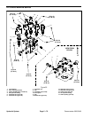
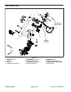
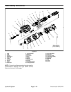
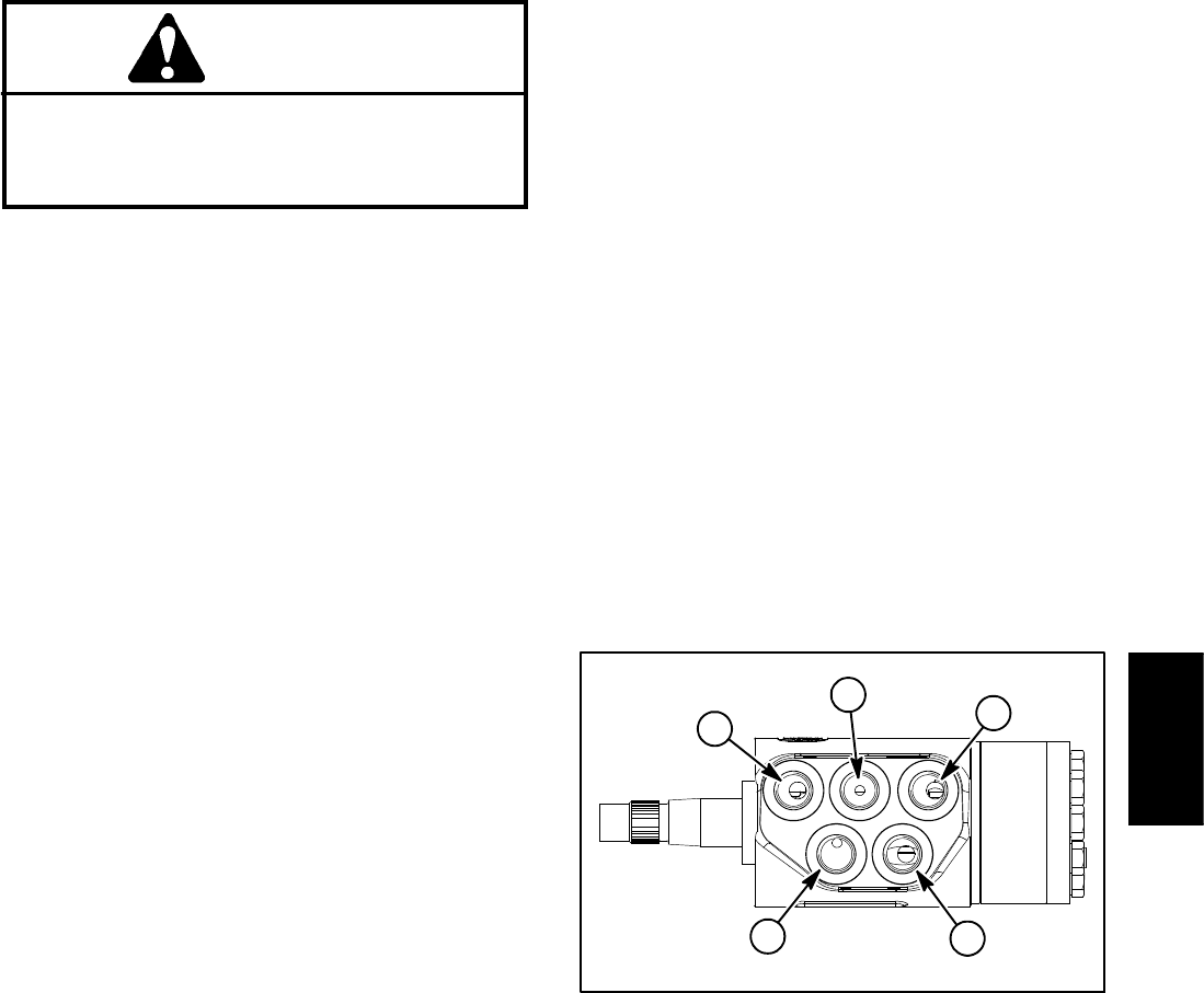
1. T port
2. R port
3. E/Ls port
4. P port
5. L port
Figure 54
2
1
3
4
5
Hydraulic
System