


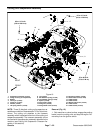

Greensmaster 3320/3420Page 7 -- 26Chassis
C. Ifliftplate (item12) wasremovedfrom A--arm,se-
cure lift plate with two (2) flange head screws (item
13). Torque screws from 67 to 83 ft--lb (91 to 112
N--m).
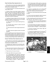
CAUTION
Be careful when assembling the suspension
counterbalance system. The counterbalance
spring is under heavy load and may cause per-
sonal injury.
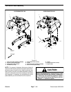
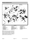
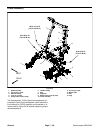
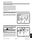
D. If clevis pin (item 26) was removed from counter-
balance mount (item23), install clevispin intomiddle
holes in counterbalance mount and below tensioner
arm (item 16). Tensioner arm can be rotated with
breaker bar or ratchet wrench (3/8” square drive) to
align holes. Figure 21 shows correct location of cle-
vis pin.
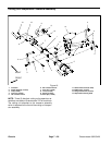
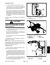
E. If stabilizer springs were removed from suspen-
sion assembly, move and support suspension as-
sembly so that upper a--a rm has stabilizer spring
attachment hole positioned 5.710” (145.0 mm) from
rearof pivotmount.Then,adjust location of spring so
the center of the spring end is 8.760” (222.5 mm)
from rear of pivot mount. Figure 23 shows dimen-
sions for correct stabilizer spring adjustment.
2. Connect the cutting unit power disconnect couplers.