


Greensmaster 3320/3420 Page 6 -- 91 Electrical System
2. Disconnect thecutting unitsfromtheelectrical power
supply by separating the cutting unit power disconnect
couplers (see Opening Electrical Circuit to Cutting Units
in the General Information section of this chapter). This
will prevent unexpected cutting unit operation.
3. To allow access to generator assembly, remove tank
mount plate assembly from machine (see Tank Mount
Plate Assembly in the Service and Repairs section of
Chapter 7 -- Chassis).
4. Remove generator drive belt (see Generator Drive
Belt (Greensmaster 3420) in this section).
5. Disconnect wire harness connector from generator
assembly.
CAUTION
Supportgenerator assemblywhen removingitto
prevent it from falling and causing personal inju-
ry. Assembly weighs approximately 50 pounds
(23 kg).
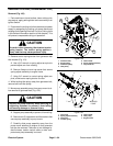
6. Support generator to prevent it from falling or shift-
ing.
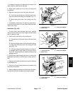
NOTE: Upper two (2) generator mounting locations on
generator plate (item 5) are slotted.
7. Loosen upper two ( 2) flange head screws (item 6)
that secure generator assembly to generator plate.
Then, remove remaining three (3) screws (item 6) that
secure generator.
IMPORTANT: Make sure to not damage the genera-
tor, fuel lines, hydraulic hoses, electrical harness,
control cables or other parts while removing the
generator assembly.
8. Carefullyraise generator assemblyto disengage up-
per two (2) screws from generator plate. Then, remove
generator from machine.
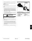
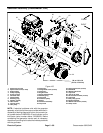
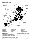
9. If necessary, remove generator pulley from genera-
tor shaft:
A. Remove cap screw (item 27) and spacer (item
25) that secure generator pulley to generator shaft.
B. Loosen the two (2) square head screws (item 4)
that secure the generator pulley to the generator
shaft.
C. Slide generator pulley from generator shaft. Lo-
cate and retrieve square key (item 2).
10.If generator disassembly is necessary, remove gen-
erator guard (item 29) fr om generator.
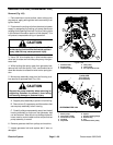
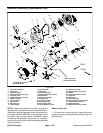
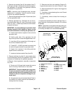
Installation (Fig. 106)
1. If removed, install generator pulley to generator
shaft:
A. Apply antiseizelubricant togenerator shaft.Posi-
tion square key (item 2) into slot in shaft.
B. Slide generator pulley onto generator shaft.
Make sure that pulley flange is positioned t owards
the generator.
C. Installandtightenspacer (item 25)and capscrew
(item 27) to secure generator pulley to generator
shaft.
D. Installtwo(2) squarehead screws(item 4)ingen-
erator pulley flange. Torque screws from 90 to 110
in--lb (10.2 to 12.4 N--m).
2. Install generator guard (item 29) if it was removed
from generator.
CAUTION
Support generator assemblywhen installing itto
prevent it fromfalling and causing personal inju-
ry. Assembly weighs approximately 50 pounds
(23 kg).
IMPORTANT: Make sure to not damage the genera-
tor, fuel lines, hydraulic hoses, electrical harness,
control cables or other parts while installing the
generator assembly.
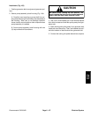
3. Loosely install upper two (2) flange head screws
(item6) intogeneratorassembly.Carefullyposition gen-
erator assembly to generator plate and engage upper
screws in generator plate slots.
4. Secure generator assembly to generator plate with
five (5) flange head screws (item 6).
5. Connect wire harness connector to generator as-
sembly.
6. Install generator drive belt (see Generator Drive Belt
(Greensmaster 3420) in this section). Make sure that
drive belt is properly tensioned.
7. Install tank mount plate assembly to machine (see
Tank Mount Plate Assembly in the Service and Repairs
section of Chapter 7 -- Chassis).
8. Check hydraulic oil level in reservoir and adjust if
necessary.
9. Connect the cutting unit power disconnect couplers.
Electrical
System