


Greensmaster 3320/3420Page 6 -- 94Electrical System
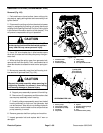
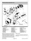
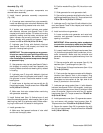
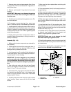
Assembly (Fig. 107)
1. Make sure that all generator components are
cleaned before assembly.
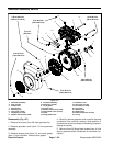
2. Install internal generator assembly components
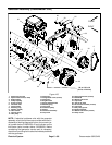
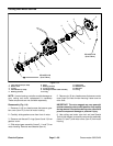
(Fig. 108):
A. If bearings were removed from rotor assembly,
install new bearings onto rotor shaft. Make sure that
new bearings are fully pressed onto rotor shaft.
B. If isolator was removed, lubricate new gasket
with dielectric lubricant (see Special Tools in this
chapter) and install to isolator. Fit isolator to housing
assembly making sure that stator conductors and
stator harness are correctly positioned in isolator.
Secure isolator with spacers and screws. Torque
screws from 35 to 45 in--lb (4.0 to 5.0 N--m).
C. Lubricate new O--ring with dielectric lubricant
(see Special Tools in this chapter) and install into
groove in housing bearing bore.
IMPORTANT: The rotor magnets are very power-
ful and can cause the rotor to shift position very
rapidly during installation. Be cautious during
rotor installation to prevent component damage
or personal injury.
D. Use generator rotor tool set (see Special Tools in
this chapter) to carefully install rotor assembly into
housing.Makessure that rotor bearing is fullyseated
in housing.
E. Lubricate new O--rings with dielectric lubricant
(seeSpecialToolsinthis chapter) andinstallO--rings
into grooves in cover. Place wave washer in cover
bearing bore.
F. Install cover to housing and secure with six (6)
flange head screws. Torque screws from 170 to 190
in--lb (19.3 to 21.3 N--m).
G. Make sure that rotor rotates before continuing
with generator assembly.
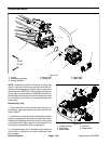
3. Install flocked seal (item 3 ) (flocked area of seal
should be toward generator), wave washer (item 4) and
retaining ring (item 5) to generator shaft. Rotate retain-
ingringtomakesureitisseatedinshaftgroove.
4. Install generator fan:
A. Make sure that tapered surfaces of rotor shaft
and fan are thoroughly clean.
B. Position woodruff key (item 22) into slot on rotor
shaft.
C. Slide generator fan onto generator shaft.
D. Securefan to generator shaftwith collar (item 15)
and flange head screw (item 16). Torque screw from
170to190in--lb(19.3to21.3N--m).
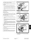
5. Lubricate new O--ring (item 24) with dielectric lubri -
cant (see Special Tools in this chapter) and install into
groove on isolator.
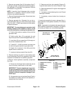
6. Install controller onto generator:
A. Lower controller onto generator and route both
controller and generator harness connectors out
opening in controller.
IMPORTANT: When securing stator conductors
to controller connectors, make sure that flange
head screws do not pinch electrical harnesses.
B. Loosely install three (3) flange head screws (item
14) that secure generator stator conductors to con-
troller connectors. Make sure that controller and
generator harnesses are positioned away from the
screws.
C. Secure controller with cap screws (item 6), flat
washers (item 7) and flange nuts (item 10).
D. Torque three (3) flange head screws (item 14) to
75 in--lb (8.5 N--m).
E. Pack controller harness connector with dielectric
lubricant (see Special Tools in this chapter). Plug
generator connector into controller connector. Insert
harnesses and connectors to the right side of the
three (3) terminals in the controller.
7. Lubricate new cover gasket (item 11) with d ielectric
lubricant (see Special Tools in this chapter). Install gas-
ket intogroove in access cover(item 12) and theninstall
cover to controller. Secure cover with two (2) washer
head screw (item 13). Torque screws f rom 70 to 80 in--
lb (8.0 to 9.0 N--m).
8. Installgeneratorcover (item17)to generator assem-
bly and secure with washer head screws (item 8).
Torque screws from 70 to 80 in--lb (8.0 to 9.0 N--m).
9. Secure fan screen (item 20) to generator fan with
four (4) torx head screws. Torque screws from 15 to 25
in--lb (1.8 to 2.8 N--m).