


Greensmaster 3320/3420Hydraulic System Page 5 -- 88
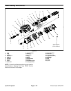
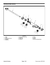
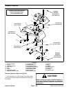
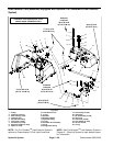
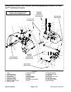
Hydraulic Reservoir
1. Tank mount plate
2. O--ring
3. Hydraulic reservoir
4. Tank cover
5. Plug
6. O--ring
7. Cap screw (4 used)
8. Neoprene washer (4 used)
9. Flat washer (4 used)
10. Overflow hose
11. Hose clamp (2 used)
12. Flange bushing (4 used)
13. Flat washer (4 used)
14. Cap screw (4 used)
15. Suction hose
16. 90
o
hydraulic fitting
17. Strainer
18. Plug
19. Breather
20. Spacer (4 used)
21. Hose clamp
22. O--ring
23. Hydraulic hose
Figure 59
v
2
3
4
5
6
7
8
9
10
11
16
17
18
15
30 to 50 in--lb
(3.4 to 5.6 N--m)
6
19
20
21
22
23
27
1
12
13
14
70 to 80 ft--lb
(95 to 108 N--m)
30 to 38 ft--lb
(41 to 51 N--m)
30 to 38 ft--lb
(41 to 51 N--m)
Antiseize
Lubricant
30 to 50 in--lb
(3.4 to 5.6 N--m)
Antiseize
Lubricant
17 to 21 ft--lb
(23to28N--m)
18
30 to 38 ft--lb
(41to51N--m)
Illustration from diesel powered
machine with serial number
below 312000000 shown
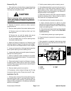
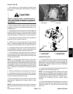
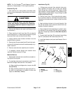
Removing Hydraulic Reservoir (Fig. 59)
1. Park machine on a level surface, set brake, lower
cuttingunits and stop engine. Removekey from theigni-
tion switch.
CAUTION
Before continuing fu rther, read and b ecome fa-
miliar with General Precautions for Removing
and Installing Hydraulic System Components in
this section.