


Greensmaster 3320/3420 Page 7 -- 25 Chassis
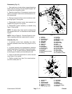
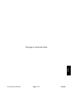
Disassembly (Fig. 20)
1. If cutting unit suspension is attached to machine:
A. Park machine on a level surface, engage the
parking brake, lower the cutting units and stop the
engine. Remove key from the ignition switch.
B. Disconnect the cutting units from the electrical
power supply by separating the cutting unit power
disconnect couplers (see Opening Electrical Circuit
to Cutting Units inthe General Information section of
this chapter). This will prevent unexpected cutting
unit operation.
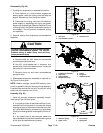
2. Remove tension from suspension counterbalance
assembly:
CAUTION
Be careful when removing tension f rom the sus-
pension counterbalance system. The counter-
balance spring is under heavy load and may
cause personal injury.
A. Remove cotter pin f rom clevis pin that secures
counterbalance tensioner arm.
B. Use 3/8” drive breaker bar in tensioner arm
square drive hole to hold tensioner arm in place so
that clevis pin can be removed.
C. Remove clevis pin and allow counterbalance
springs to relax.
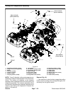
3. Disassemble suspension assembly as required us-
ingFigure20asaguide.
NOTE: Medium strength Loctite #609 retaining com-
pound is applied to ball joint housing during assembly.
Localized heat around the ball joint housing will allow
easier ball joint removal from A--arm.
Assembly (Fig. 20)
1. Install all removed suspension assembly compo-
nents using Figure 20 as a guide.
A. Ifany ball joint(item3) wasremoved fromA--arm,
clean ball joint housing and A--arm bore with Loctite
cleaning solvent (or equivalent) and allow to dry. Ap-
ply Loctite #609 retaining compound (or equivalent)
to ball joint housing before inserting ball joint into A--
arm.
B. If any clamp (item 9) was removed, make sure
thatraised boss inclampbore is positioned ingroove
of ball joint stud before securing clamp.
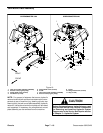
1. Clevis pin
2. Counterbalance mount
3. Tensioner arm
Figure 21
2
1
3
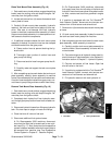
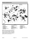
1. Suspension assembly
2. Cap screw
3. Spring retainer
4. Flange head screw
5. Spacer
6. Flange nut
7. Stabilizer spring
Figure 22
1
3
5
7
4
6
2
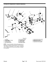
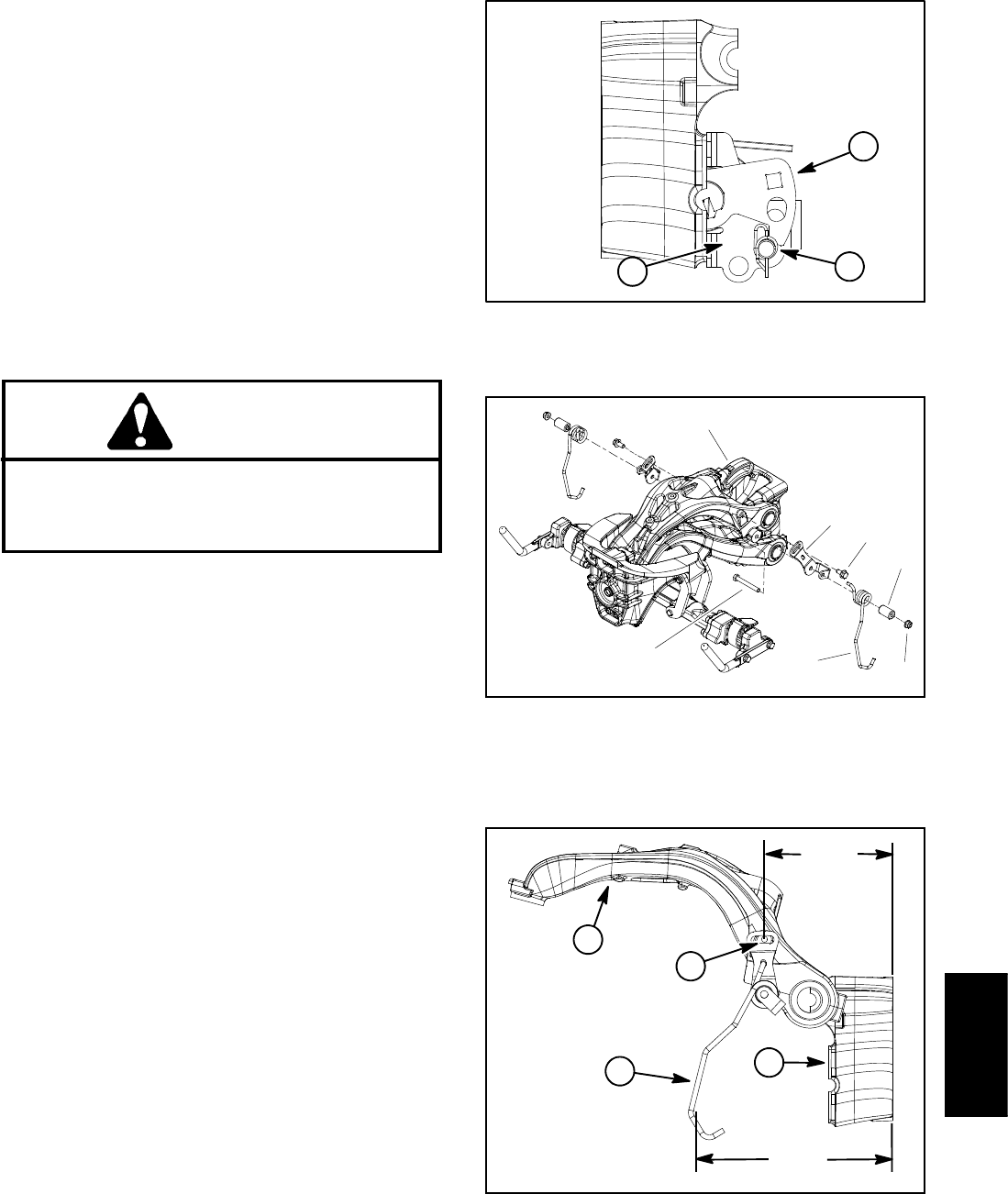
1. Stabilizer spring
2. Upper a--arm
3. Pivot mount
4. Spring hole
Figure 23
2
1
3
8.760”
(222.5 mm)
5.710”
(145.0 mm)
4
Chassis