


Greensmaster 3420 Page 4 -- 17 Diesel Engine
3. Close fuel shut--off valve on fuel tank.
4. Remove air cleaner and air intake hose from ma-
chine (see Air Cleaner Removal in this section).
5. Remove radiator from machine (see Radiator Re-
moval in this section).
6. Remove exhaust system from machine (see Ex-
haust System Removal in this section).
7. Remove starter motor from engine (see Starter Mo-
tor Removal in this section).
8. Disconnect fuel supply hose from the injector pump
and fuel return hose from the #3 injector. Drain any fuel
trapped in the hoses into a suitable container. Remove
hoses from grommets in engine support on front of en-
gine. Plug hoses and position them away from engine
assembly.
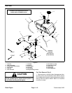
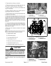
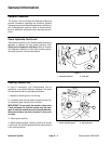
9. Loosen screw thatsecures the throttle cable to swiv-
el on injector pump speed control lever. Disconnect
cable from swivel and cable bracket (Fig. 12). Position
cable away f rom engine.
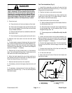
10.Disconnect wire harness connectors from engine
components:
NOTE: Before disconnecting wire harness connectors,
label all electrical leads for assembly purposes.
A. Negative battery cable.
B. Wire harness ground.
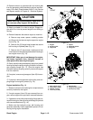
C. Fuel stop solenoid (Fig. 13).
D. Glow plug bus (Fig. 13).
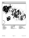
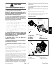
E. Alternator connector and stud (Fig. 14).
F. Temperature sender (Fig. 13).
G. Oil pressure switch (near oil filter) (Fig. 14).
CAUTION
Support the hydraulic pump, bell housing and
generator assembly before removing any sup-
porting fasteners to prevent the assembly from
shifting and causing component damage or per-
sonal injury.
11.Support hydraulic pump, bell housing and generator
assembly to prevent it from moving during engine re-
moval.
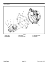
Figure 12
1. Throttle cable
2. Speed control lever
3. Cable jam nut
4. Throttle cable swivel
4
2
1
3
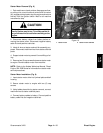
Figure 13
1. Fuel return hose
2. Throttle cable swivel
3. Fuel stop solenoid
4. Glow plug bus
5. Temperature sender
1
4
5
2
3
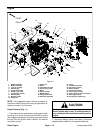
Figure 14
1. Alternator stud
2. Alternator connector
3. Starter motor solenoid
4. Fusible link harness
5. Oil pressure switch
3
4
1
2
5
Diesel
Engine